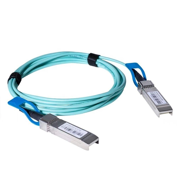
It plugs into network equipment (like switches, routers, or servers) and its primary function is to convert electrical signals from the device into light signals for transmission over fiber optic cables, and then convert received light signals back into electrical signals. People can also refer to an optical transceiver as a fibre optic transceiver or optical module. A transceiver is a mix of the words 'transmitter' and 'receiver. ' An optical transceiver includes an optical. This section explains the core IP and optical components used in traditional hierarchical networks. It helps readers understand the router, transponder, ROADM, amplifier, and management elements that form the baseline network architecture. In fiber optics, this data is sent in the form of pulses of light over an optical fiber, at very high speeds and across long distances. Essentially, these devices. Why choose Nokia for your optical network? The Nokia industry-leading optical network portfolio leverages highly vertically integrated coherent optical engines and includes the latest generation of open and flexible optical line systems, intelligent coherent pluggables, ultra power-efficient. This page provides an introduction to optical wireless networks. It compares short-range (directed and diffused) and long-range optical wireless technologies, highlighting their differences. The broadband wireless.
[PDF]
An optical network is a communication system that leverages light to convey information across distances, encoding data into rapid flashes of light instead of relying on electrical voltage changes. At the heart of this ecosystem lies the Optical Transport Network (OTN) — a framework defined by the ITU-T (notably G. 709) that has become the foundation for modern optical communications. This method allows engineers to manage the exponential growth in global data traffic generated by. A passive optical network (PON) is a system commonly used by telecommunications network providers that brings fiber optic cabling and signals all or most of the way to the end user. Depending on where the PON terminates, the system can be described as fiber to the curb, fiber to the building or. An Optical Transport Network (OTN) is a transmission network based on wavelength division multiplexing (WDM) technology. It is a specific type of transmission network that transmits data and manages it using optical signals. OTN is built on a series of protocols, including G. It is designed to provide a high-speed, scalable, and reliable infrastructure for the transmission of data between different network nodes. While there are many subtle differences, a clear distinction between active optical networking and PON topology is PON's use of a.
[PDF]
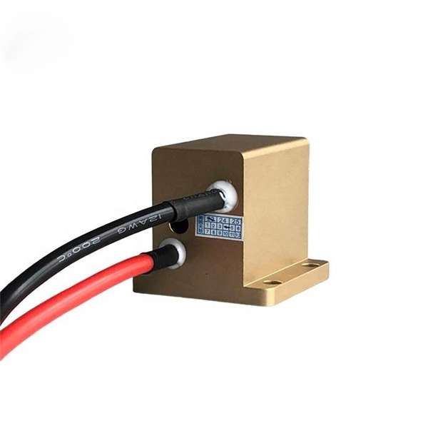
Connect the red wire to the copper wire with the red color bar of the optical/electrical composite cable, and connect the black wire to the other copper wire of the optical/electrical composite cable. Then press and secure the crimp tube. Ensure that no copper. The composite fiber optic cable is a type of cable that combines both fiber optic and copper conductors within a single cable sheath. This hybrid construction allows for the simultaneous transmission of data using fiber optics and electrical power or additional data using copper conductors. How to Use the Composite Fiber Optic Cable? To begin, you need to gather all the accessories and equipment required: 1. Waterproof Industrial-Grade Fiber PoE Media Converter Compatible with the IEEE802. Cut the cable along the center and pull one copper cable on the left and right sides to the position shown in the figure to expose the optical fiber. Whether you're a seasoned technician or a beginner, this guide has something for everyone. more In this video, we'll walk you. In a previous blog, we covered what to do when you need to connect a device that is located beyond the 100-meter distance requirement and described four ways to address the problem—a new TR, the use of an extender device, extended-reach copper cable and fiber. This article will guide you through the necessary tools, materials, and methods on how to connect fiber optic cables effectively.
[PDF]
Scattering accounts for the greatest amount of attenuation in a fiber cable, between 95 and 97 percent. Light traveling through the fiber interacts with the densities as shown in the light and is then partially scattered in all directions. Fiber optic cables have many advantages, but one of the downsides just like with copper cable, is that it can experience what is called attenuation. Attenuation refers to the loss of light as it travels down the fiber. This can be due to a variety of factors: scattering and absorption, intrinsic. This attenuation is inevitable, so the smaller the attenuation value, the longer the transmission distance of the same optical power. The better the quality of this fiber patch cable. It indicates the amount of signal reflected back. At TREND Networks, we are frequently asked how much loss is allowed when conducting testing on fiber optic cabling. Unfortunately, it is not a simple answer and depends on several factors. So how do you determine acceptable loss? When testing fiber optic cabling, determining acceptable loss is. Understanding fiber loss is vital in maintaining a reliable, efficient network. Understanding it is crucial for anyone involved in data centers, telecommunications, or enterprise networking. Here are the details and instructions about each field and how they contribute to the calculation: 1. Attenuation Coefficient (dB/km): This value represents the inherent signal loss per kilometer of.
[PDF]
Optical Fiber Cable & Accessories Price in Nepal, Kathmandu. Buy with best and reasonable price @ ITShop Nepal. Nepal - Shop for Best Online at Daraz. np Wide Variety of fiber optical cables. Great Prices, Even Better Service. Copyright © 2026 Janaki Cable Industry. Powered by one tech® View the latest retail rates for Janaki Cable products effective from Apr 20 2026. Includes per-meter prices for Copper/Aluminum Armoured Power Cables, Multistrand Flexible Wires, and FRLS Cables. The Nepalese optical fiber cables market fell slightly to $X in 2025, dropping by X% against the previous year. This figure reflects the total revenues of producers and importers (excluding logistics costs, retail marketing costs, and retailers' margins, which will be included in the final consumer. SÜRGÜLÜ PATCHPANEL SC UPC DUBLEX 24XADAPTÖR 48XPIGTAIL RAL7035 1u 19” MEK. SÜRGÜLÜ PATCHPANEL SC UPC DUBLEX 12XADAPTÖR 24XPIGTAIL RAL7035 Buy Fiber Optic Infrastractures and Accessories in Nepal at best price from platforms Hub. is a leading Internet & TV service provider in Nepal. Since 24 years, Vianet Communication has always remained at the forefront, providing reliable and affordable Fiber Broadband Internet Services.
[PDF]

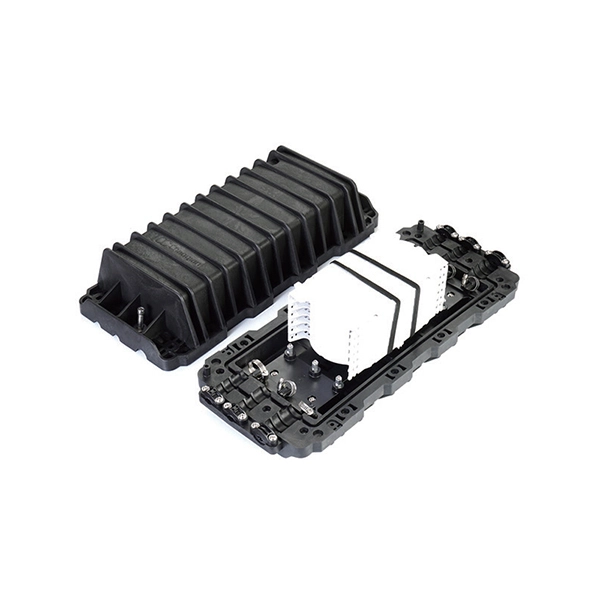
In this step-by-step tutorial, we show you exactly how to place a fusion splice safely and securely inside a Coyote fiber optic splice enclosure. Fiber cable splicing is a critical step in building reliable fiber optic networks. Whether in data centers, telecom rooms, or outdoor FTTx deployments, proper splicing inside a fiber enclosure ensures low signal loss, long-term stability, and easy maintenance. This guide explains what fiber cable. Think of a fiber optic cable splice as the seamless stitching that keeps data flowing through the delicate threads of a network—like a master tailor joining fabric with precision. Whether repairing a broken cable or extending a fiber run, fiber optic splicing ensures light signals travel. In addition to the outer skin of the optical cable (if any, please remove the shielding and armoring) and then remove each wrapping layer until the loose tube is exposed. Make sure you read and understand this instruction as well as instructions provided with related assemblies before. In this guide, we cover the basics of fiber optic splicing, how to perform splicing using two different methods, and finally some best practices to perform good fiber splicing. What is Fiber Optic Splicing and Why is it Needed? – #1. Use and Maintain Your.
[PDF]
Typical rates range from $0. 00 per ft depending on terrain, access, and required precision for termination. Basic — 1,000 ft single-mode run indoors with minimal termination: Cable $0. 00/ft, Permits $150, Accessories $100. Total ≈. Fiber-optic cable materials typically cost $1 to $6 per linear foot, depending on fiber count and cable type. Commercial building installations with 100-200 network drops generally range from $15,000 to $30,000. Single-mode fiber costs less per foot than multimode fiber, but it requires more. Packaging should be the same as what is found in a retail store, unless the item is handmade or was packaged by the manufacturer in non-retail packaging, such as an unprinted box or plastic bag. See the seller's listing for full details. 43FedEx Ground or FedEx Home Delivery®. See detailsfor. The unit cost of fiber optic cables can vary from $0. Here's a general pricing reference: Cable TypePrice Range (USD/meter)Simplex / Duplex Indoor Cable$0. 50Multimode (OM1/OM2/OM3)$0. Main cost drivers include cable grade (indoor vs outdoor, armoured), distance, and labor for trenching, splicing, and termination. Custom-built. Uses item details. Price when purchased online Shop for Optical Audio Cables in TV Accessories. Buy products such as VANAUX Optical Audio Cable, TOSLINK S/PDIF Digital Optic Cord, Fiber Audio Cable, Gold-Plated, Nylon Braided for Home Theater, Sound Bar, TV, PS4, Xbox, PlayStation (10ft/3m) at.
[PDF]

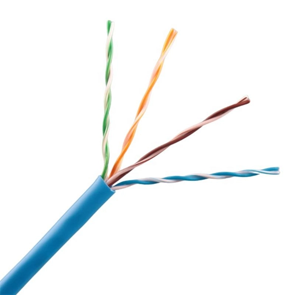
For most setups, cables with 12, 24, or 48 cores are common choices, ensuring compatibility with modern equipment and ease of management. Fiber cores are the heart of fiber optic cables, transmitting light signals that carry data. Made from either high-quality glass or plastic, the core plays a critical role in determining the cable's performance. The total number of cores for a 1pc fiber patch cable is calculated as the number of. In fiber optic cables, data is transmitted as pulses of light that travel along a thin strand of glass or plastic fiber. The light is typically. The number of optical cores in an optical fiber is the total number of equipment interfaces multiplied by 2, plus 10% to 20% of the spare quantity, and if the communication mode of the equipment has serial communication and equipment multiplexing, you can reduce the number of cores. The following ZR Cable introduces some methods to determine the number of fiber cores. First of all, clearly know the number of wiring points in this layer, calculate the number of switches, and whether the connections. A fiber-optic cable, also known as an optical-fiber cable, is an assembly similar to an electrical cable but containing one or more optical fibers that are used to carry light. ” However, when light enters the core it needs to remain within it, and one layer that ensures that is called.
[PDF]
Genuine Modules mentions that the cost of fiber optics per kilometer can range from $10,000 to $50,000, depending on various factors such as the type of fiber, installation method, terrain, and region. Fiber-optic cable materials typically cost $1 to $6 per linear foot, depending on fiber count and cable type. Commercial building installations with 100-200 network drops generally range from $15,000 to $30,000. Single-mode fiber costs less per foot than multimode fiber, but it requires more. The price of fiber optic cabling depends on cable type, length, installation method, and surrounding materials. Typical costs hinge on fiber count, indoor versus outdoor use, and whether trenching, splicing, or termination is required. This guide provides practical ranges in USD and practical price. Discover 6 core fiber optic cable 1km price with GYXTW armored outdoor design, G652D fiber, CE/ROHS, ideal for 5G FTTH networks. Knowing how much fiber optic cable costs, which factors can impact cost, and key cost considerations can help you avoid unnecessary expense and get the most out of your budget. 50 per meter, depending on several variables. Here's a general pricing reference: These are indicative prices based on standard configurations. Custom-built cables or niche specifications can lead to higher prices. 30Single-mode Outdoor Cable$0. 50Multimode (OM1/OM2/OM3)$0.
[PDF]

The transmitter optical power ranges from +3 to +7 dBm, while receiver sensitivity reaches -30 dBm, supporting distances up to 20 kilometers over standard single-mode fiber infrastructure. Note 1: Measured with 1310nm, 1. 244Gbps PRBS223- 1 burst-mode optical input, ER= 10dB, BER= 1x10⁻¹⁰; Single burst packet length is 40us and packet interval is 40us. Note 2: Input optical power level difference of adjacent burst packets. Note 3: Receiver optical power ranged from -8dBm to -28dBm. designed for FTTH GPON applications. Packaged in a Small Form- infrastructure in edge, enterprise, or distributed environments. robust fiber-to-the-home (FTTH) or small-scale fiber deployments. temperature, voltage, bias current, and optical power. On the uplink side, it operates. Max. Supporting 20km over single-mode fiber with 1490/1310nm wavelengths, this module delivers 33 dB link budget for 1:64 or 1:128 split ratios at 2. 488 Gbps downstream and 1. SC/PC connector for OLT PON port integration. Complete technical specifications and product details Our. Cisco ME Series products support any fiber-based (FTTx) access scenarios, including Fiber To The Home (FTTH), Fiber To The Building (FTTB), Fiber To The Curb (FTTC), Fiber To The cell (FTTc), and Fiber To The business (FTTb). Figure 1 illustrates the Cisco GPON solution. The Cisco GPON. The following tables list the performance specifications for the various functional blocks of the integrated optical transceiver module.
[PDF]
To know how much wire or cable will fit on a shipping reel, enter the diameter of your cable in inches below. Our Reel Capacity Calculator will show how many feet or meters of that cable will fit on our different reels. Still have questions about reel size?. When placing an order, it's important to know how many reels you can expect. With our easy cable reel capacity calculator, you can calculate the maximum reel, spool or drum capacity. All you need is to enter the reel (drum) dimensions and the diameter of the cable. Please note that. It is often necessary to determine how much of a given cable or wire will fit onto a spool or reel. This article provides a relatively simple method to calculate the approximate maximum length if you know the cable's diameter and the reel's dimensions. Providing wire or cable on reels or spools is. An Equal Opportunity Employer to include women, minorities, veterans, persons with disabilities, color, sex, sexual orientation, gender identity, religion, origin, and genetic information. Priority Wire & Cable supplies wire & cable from the largest stock in the U. and offers same day shipping. Fiber optic cables can be custom cut by Proterial Cable America or distributor to match your required lengths for each cable run. Alternatively, you can order a reel matching the total length needed and cut your own segments as necessary.
[PDF]

In this guide, we'll walk you through the entire process of preparing fiber optic cable for splicing and termination to fiber connectors. We'll explore the necessary tools, safety precautions, and step-by-step procedures for cable connectors, mechanical and fusion. At the heart of any robust fiber optic network lies a crucial process: Preparing a fiber cable for termination of a connector or splice. Two types of splices are used in fiber optic cabling one is Mechanical the other is Fusion. Whether you're installing a new network, expanding an existing one, or. Splicing fiber optic cable is an extremely important phase for making dependable, high-speed communication infrastructures. Regardless of the type of fiber network you're deploying, be it for telecom, enterprise data centers, or smart city infrastructure, fusion splicing provides the benefits of. Think of a fiber optic cable splice as the seamless stitching that keeps data flowing through the delicate threads of a network—like a master tailor joining fabric with precision. This article explains when. We terminate fiber optic cable two ways - with connectors that can mate two fibers to create a temporary joint and/or connect the fiber to a piece of network gear or with splices which create a permanent joint between the two fibers. These terminations must be of the right style, installed in a. So in essence, fiber optic splicing is a process used to join two separate fiber optic cables together.
[PDF]
Main cost drivers include cable grade (indoor vs outdoor, armoured), distance, and labor for trenching, splicing, and termination. This guide presents ranges in USD and practical price estimates to help budget planning. Indoor OM3/OM4 vs outdoor armoured increases price. This guide outlines the major factors that influence fiber optic cable costs and provides practical tips for estimating pricing in bulk or project-based scenarios. Content 1 What's the Typical Price Range? 2 1. Fiber Count and Cable Construction 3 2. Fiber. Fiber-optic cable materials typically cost $1 to $6 per linear foot, depending on fiber count and cable type. Commercial building installations with 100-200 network drops generally range from $15,000 to $30,000. Single-mode fiber costs less per foot than multimode fiber, but it requires more. Buyers typically pay for fiber optic cable by length, fiber type, and installation complexity. Data aggregated from Q1 2026 contractor invoices across Texas, Ohio, and North Carolina. Cost per foot of fiber. Typically, per drop fiber cabling prices range from $250 – $1000 per drop depending on the type of fiber (OM2, OM3, OM4, or OM5), multi or single mode, PVC or plenum, average drop length, and also the number of fibers in each cable. Adding switches, high-end enclosures and other issues can also.
[PDF]