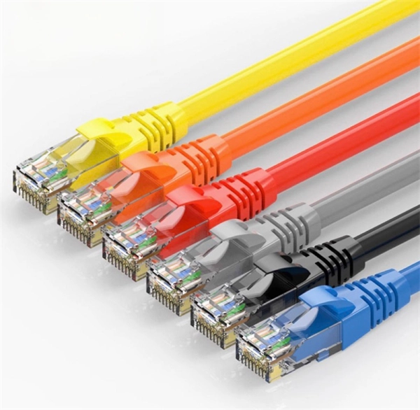
These installation instructions provide overview and specification information for small form-factor pluggable (SFP/ SFP+/SFP28) modules, as well as instructions for installing and removing the modules. SFP (Small Form-factor Pluggable) transceivers are essential components in modern fiber optic networks, enabling network devices such as switches, routers, and servers to transmit and receive data over optical fiber. By converting electrical signals into optical signals—and vice versa—SFP. Gigabit single-mode fiber optic module Common parameters of optical modules 1. Center wavelength 1) 850nm (MM, multi-mode, low cost, but short transmission distance, usually only 500M); 2) 1310nm (SM, single mode, large loss during transmission, small dispersion, generally used for transmission. As a leading provider of fiber optic solutions, Weunion offers a wide range of SFP-compatible products, including optical transceivers, DAC/AOC cables, LC patch cords, and MPO/MTP assemblies. While they may appear to be simple plug-in transceivers, SFP modules are precision-engineered devices that directly influence network. o In optical modules, "core" refers to the light-transmitting channel in the fiber. A 1-core module uses a single fiber core for data transmission, while a 2-core module uses two cores. o Think of a highway. A 1-core fiber is like a single-lane road—only one car (or data signal) can travel at a.
[PDF]

In this guide, we break down the two core stages of optical fiber manufacturing: preform production (shaping the precursor material) and fiber drawing (transforming the preform into thin, usable fiber). Optical fiber preforms are the starting point behind every kilometer of fiber optic cable. Though rarely seen by end users, these cylindrical glass rods serve as the base material from which high-speed optical fibers are drawn. As global communication relies more than ever on fiber networks—from. 📦 For purchasing, use the RP Photonics Buyer's Guide for fiber preforms. It provides an expert-curated supplier directory, buyer-focused technical background information, and structured selection criteria to support professional procurement decisions. During the fiber drawing process, the preform is heated and drawn into a. The production of optical fiber is a precision-driven process that transforms raw materials like silicon tetrachloride into ultra-thin, high-performance fibers capable of transmitting terabits of data over thousands of kilometers. Who invented optical fiber and when? Corning scientists Dr. Peter Schultz, and Dr.
[PDF]
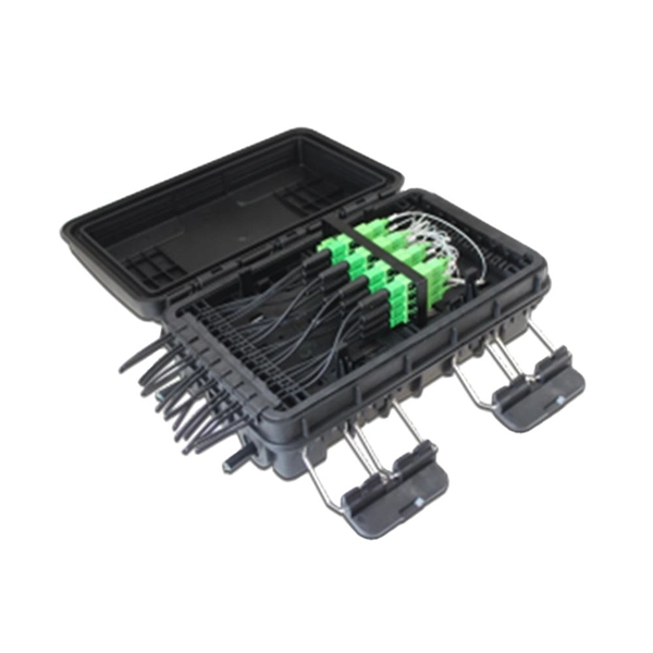
Learn how to install a fiber optic termination box step-by-step for FTTH projects. Covers mounting, splicing, routing, labeling, and testing for indoor/outdoor use. Installing a fiber optic termination box is one of those jobs that looks simple on paper, but it's easy to do. A common question we receive is: How do you use a fiber-optic termination box? We recommend using a termination box if you're ordering an assembly with more than two strands. It helps keep your connectors free from contamination and dust, while also keeping your assembly neat and organized. Check. A Fiber Termination Box, also known as a Fiber Distribution Box, is a crucial component in fiber optic networks. They also feature resistance to moisture, impact, chemical exposure. Whether you're a network technician, IT professional, or simply looking to understand fiber optic networks better, this guide will provide you with the essential knowledge for working with fiber termination box.
[PDF]

It operates by emitting a bright and visible red laser light into the fiber and detecting the location of faults by observing the light leaking out of the fiber. It is also possible to locate faults in OTDR dead zones and perform fiber identification from one end to the other. When it comes to testing fiber optic cables, a Visual Fault Locator (VFL) is an essential tool in your toolkit. It's a cost-effective and. Whether you're a seasoned technician or a fiber enthusiast, a VFL is the first step to make your life easier in troubleshooting a fiber optic cabling issue. We will be explaining what The VFL's primary purpose is, and how best to use it. Below are some key use cases for a VFL. It gives instant visual proof of where light escapes the fiber. Even beginners can spot bends, cracks, or bad splices without complex tools. A visual fault locator saves time, cuts stress, and reduces repeat work., optical fiber fault detector, optical fiber fault test pen) is a 650nm (± 20nm) semiconductor laser as a light-emitting device, which emits stable red light through a constant current source drive, and connects with the optical interface into the optical fiber, so. In the world of fiber optic communication, diagnosing and troubleshooting network issues is essential to maintain smooth connectivity. Whether you are a beginner or a professional working with fiber optics.
[PDF]
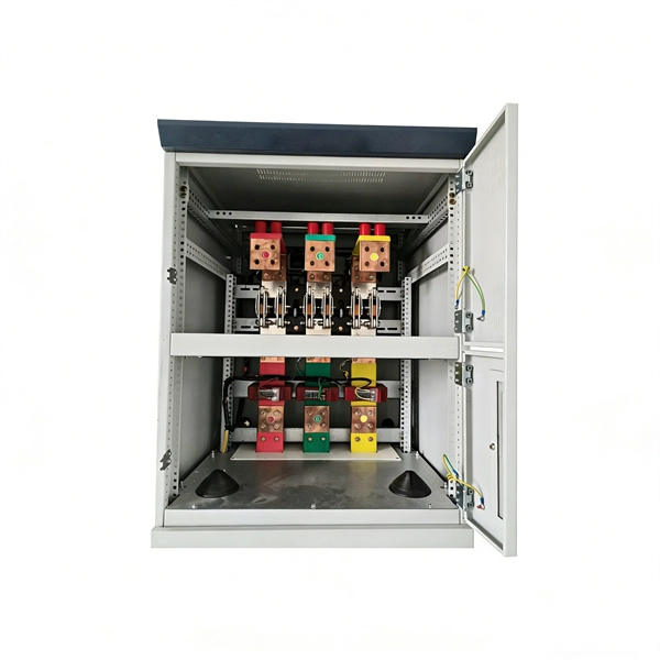
This comprehensive guide will delve into the most effective practices, key considerations, and strategic approaches for designing and implementing an efficient cabling system within a data center environment. At the core of data center connectivity are fiber optic cables, which are thin strands of plastic that transmit data using light signals or wavelengths, offering unparalleled speed and efficiency. The data superhighway paved by fiber optics forms the backbone of modern data centers, ensuring rapid. An end-to-end cabling system is an ideal solution for data centers especially when time for traditional cable installation and termination is limited. Explore advanced configurations, testing protocols, and industry best practices. As the demand for data surges, these switches become more vital in sustaining networks that are efficient, scalable, and. As data centers continue to grow in complexity and scale, efficient fiber optic cabling is essential for maintaining high performance, reliability, and scalability. Proper planning and implementation of cabling infrastructure can significantly reduce downtime, improve airflow, and ensure. center hardware layout design. This map should include the cabinet placements, patch panels, hardware, port-counts, trunking locations and power access connection points. Future plans for change will be discussed, as well as the bandwidth required. infrastructure design. The design's intent is to.
[PDF]

When it comes to testing fiber optic cables, a Visual Fault Locator (VFL) is an essential tool in your toolkit. A VFL is used to detect faults, breaks, or bends in fiber optic cables by emitting a bright red light that is visible even through the fiber's jacket. It's a cost-effective and. A Visual Fault Locator which can be also called visual fault identifier (VFI), fiber fault locator, fiber fault detector, etc., is a visible red laser light designed to inject visible red light energy into an optical fiber. Using a VFL to diagnose issues can save time and cost when diagnosing an. A visual fault locator is a compact, handheld device that emits a visible light beam, typically in the red wavelength range, through a fiber optic cable. It works by injecting a visible red laser light into the fiber, which can be seen through the jacket or at the end of the cable. If the light doesn't come out the other side, there might be a problem. You. And in the end we will show you how to use an old cell phone's camera to detect light in a fiber optic system. It uses a bright incandescent bulb or visible LED source to.
[PDF]
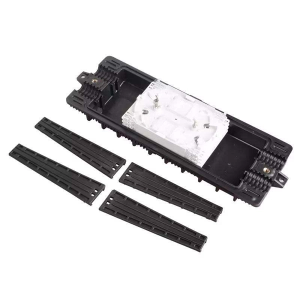
Learn how to splice 4-fiber optic cables using ODF in this complete step-by-step tutorial. Whether you are a beginner or a professional in fiber optic networking, this guide will help you splice fiber cables accurately, manage connections with ODF panels, and ensure. This complete guide explores everything you need to know about ODFs — from their structure, types, and key components, to installation best practices and modern design trends. Whether you're building a central office, data center, or FTTx distribution network, understanding the right ODF. How to Splice 4-Fiber Optic Cable with ODF | Step-by-Step Fiber Optic Splicing Tutorial. This guide demystifies ODF, exploring their design, core functions, types, and how they. An Optical Distribution Frame (ODF) is the central hub for fiber splicing, termination, patching, and cable protection in modern optical networks. It's where incoming and outgoing cables meet. It does four key things: Think of it as the central hub for your fiber network. Without it, cables get tangled. This article explores the types, components, applications, installation, and maintenance best practices, providing a.
[PDF]

This wikiHow article will teach you how to splice a cut fiber optic cable back together with a fiber optic stripper and cutter and a fiber optic crimper. Trim off any frayed or damaged ends of the cable. While a cut or damaged fiber optic cable can temporarily take your network down, it is possible to quickly fix the cable with the right tools. When fiber cables sustain damage, specialized repair techniques help restore connectivity and maintain data integrity. This comprehensive guide outlines professional fiber optic repair protocols that align with industry best practices. Adhering to precise methodologies, we can mend impaired cables. Get your fiber optic cable repair tools together. You'll need strippers, cleavers, splice trays, a splicing machine, and cleaning materials like alcohol wipes. Leave some extra cable before the damage point. It makes cutting and splicing easier. However, you don't need to panic! It can still be fixed. If you have the right tools and knowledge, you can definitely find the solution. Understanding the causes and types of fiber optic cable damage helps detect. Whether you're a network technician, IT professional, or telecom operator, you'll find practical steps, tools, and tips to restore connectivity with minimal loss. Dekam Fiber's state-of-the-art solutions, including our UltraRepair kits, make these processes accessible and reliable.
[PDF]

This complete guide covers everything from identifying causes of failure to advanced repair techniques, drawing on the latest industry standards and innovations. A fiber termination box is the standard instrument used in fiber optic networks to connect, secure, and protect optical fibers at the terminating point. Proper installation and maintenance of FTBs are essential to ensure the reliability and performance of the network infrastructure. Before. By understanding these key elements and following the outlined steps, you can effectively repair fiber optic cables and maintain the high-performance network necessary for today's demanding communication needs. Whether you're a network technician, IT professional, or telecom operator, you'll find practical steps, tools, and tips to restore. FTTP or fiber To The Premises applications have reinforced the importance of reliable and stable fiber optic terminations. Good quality fiber laying and termination systems help achieve minimal back reflection and low signal loss. They also feature resistance to moisture, impact, chemical exposure. A fiber optic distribution box, also known as a fiber optic terminal box or fiber optic termination box, is a device used to connect and manage fiber optic cables in a network. The distribution box provides.
[PDF]
Use the MTEXT command in AutoCAD to create and edit multiline text with formatting, columns, styles, and fields. Learn when to use MTEXT instead of TEXT. I'm wanting to create documentation for a control fiber optic network. Can anyone help me out? Some examples of a diagram would also help. 10-27-2018 01:41 AM Do you know if there's some symbol standard. Search by part number or description such as CAT5, CAT6, OSP, etc. Sort by any of the table headers. Use the drop down menu to filter by product category and type. Sort by any. Be among the first to receive important product updates, insights and news. Discover all CAD files of the "Optic fiber connectors" category from Supplier-Certified Catalogs ✅ SOLIDWORKS, Inventor, Creo, CATIA, Solid Edge, autoCAD, Revit and many more CAD software but also as STEP, STL, IGES, STL, DWG, DXF and more neutral CAD formats. Free CAD and BIM blocks library - content for AutoCAD, AutoCAD LT, Revit, Inventor, Fusion 360 and other 2D and 3D CAD applications by Autodesk. CAD blocks and files can be downloaded in the formats DWG, RFA, IPT, F3D. You can exchange useful blocks and symbols with other CAD and BIM users. The two linetypes are shown below. The appearance is similar but slightly different. Does anyone have such a code that they could share with me? I struggled for an hour or so and came up with this. There is a small gap on the left side of the circle.
[PDF]

In this step-by-step tutorial, learn how to splice fiber optic cables like a pro — perfect for telecom technicians, network engineers, and field techs. more 🔧 Watch a real-time fiber optic splicing demo in action!. Fiber cable splicing is a critical step in building reliable fiber optic networks. Whether in data centers, telecom rooms, or outdoor FTTx deployments, proper splicing inside a fiber enclosure ensures low signal loss, long-term stability, and easy maintenance. This guide explains what fiber cable. In this guide, we cover the basics of fiber optic splicing, how to perform splicing using two different methods, and finally some best practices to perform good fiber splicing. What is Fiber Optic Splicing and Why is it Needed? – #1. Whether repairing a broken cable or extending a fiber run, fiber optic splicing ensures light signals travel. Regardless of your level of experience, creating high-quality, high-performance fiber optic networks requires developing your skills in fusion splicing. This guide reveals the secrets to fusion splicing with little fluff—just proven, straightforward techniques refined from years of work in the.
[PDF]
Tilt sensors are devices that measure the tilt or slope of an object with respect to a reference. Fibre Bragg Grating (FBG) tilt sensors are a specific type of tilt sensor that utilizes the principle of Bragg's law in fiber optics to measure tilt angles. The tilt sensor is composed of two cylindrical floats suspended in water, connected with FBG. When the external environment causes the tilting of the sensor. Abstract—A surface-mounted tilt sensor was designed and fabricated to measure the inclination angle of engineered structures or slopes in two directions. In a FBG tilt sensor, the optical fibre is. We demonstrate a new concept for an all-fiber inclinometer based on a tapered fiber Bragg grating (tFBG) in a fiber ring laser (FRL) with the capability of measuring the tilt angle and temperature simultaneously.
[PDF]
This guide walks you through the complete fiber installation process, from checking availability to optimizing your Wi-Fi network performance. Upgrading to fibre internet involves replacing your existing copper cables with new fibre-optic ones. This upgrade brings faster speeds and more reliable connectivity. Here is what the installation process is like: One of our technicians will visit your home, remove the old copper wiring and. If you need Fiber Optic Cable Installation in Malta or areas close by allow us to assist you by connecting you with specialized pros who can do the work you request. Step 1: Planning Before any installation begins, thorough planning is essential. This includes determining the network's requirements, such as bandwidth, distance, and the number of. This guide will explain the entire set of activities involved in installing Fiber optic cable contractors -from the early planning stage right through testing-for facility managers, IT teams, and low-voltage contractors to build high-performance networks safely and efficiently. The processes. The Fiber Optic Association, Inc. (FOA) was founded in 1995 to help develop the workforce to build the fiber optic networks to support a rapid expansion in communications and the Internet. The charter of the FOA was to promote professionalism in fiber optics through education, certification, and. We offer :- For more information email us on sales@merlin.
[PDF]

