In this video, we'll walk you through the process of wiring a home distribution box with a detailed connection diagram. Whether you're an electrician or a DIY enthusiast, this guide will help you understand the basics of home electrical distribution. more Welcome to our channel! In this video. An electrical panel box, also known as a breaker box or a distribution board, is a crucial component of any electrical system. It serves as a central hub for distributing electricity throughout a building, ensuring that power is delivered safely and efficiently to all the required locations. What is Distribution Board? Distribution board. Hey, in this article we are going to see the Single Phase Distribution Box Wiring Diagram and Connection Procedure. And all the switching and protective devices are installed in the. Are you ready to master the skill of building electrical panels? This detailed guide provides an excellent base for beginners. Learn about the essential components of panels, such as the circuit breakers and fuses that safeguard against hazards. Then, delve into complex wiring configurations. Single Phase wiring installation is the most common wiring in residential buildings. In Single Phase supply (230V in UK, EU and 120V & 240V in the US & Canada), there are two (one is Line (aka Phase, Hot or Live) and the other one is Neutral) incoming cables from the utility poles to the kWh energy.
[PDF]
Multimode fiber optic cable has a larger core, typically 50 or 62. 5 microns that enables multiple light modes to be propagated. Because of this, more data can pass through the multimode fiber core at a given time. The maximum transmission distance for MMF cable is around 550m at the speed of. Multimode Fiber (MMF) has a core diameter, typically 50–100 micrometers, has ability to transfer multiple modes of light through the fiber core, uses lower-cost electronics (LED, VCSEL) operates at the 850 nm and 1300 nm wavelength and is used for short distance interconnections (up to 550m). This Applications Engineering Note (AE Note) discusses the criteria for properly selecting the optimal multimode fiber (MMF) for enterprise applications. Both fiber types play essential roles in today's optical.
[PDF]
As light in fibers often does not have a well defined polarization state, it is important that a fiber-optic attenuator exhibits only a minimum amount of polarization dependence. Generally, the obtained insertion loss has some dependence on the optical wavelength. Some attenuators have a relatively strong wavelength dependence and are made for working in narrow wavelength regions, e.g. with a bandwidth of only 20 nm around a center wavelength of 1550 nm. Others are optimized for a weaker wavelength dependence, making them u. For single-mode devices, the insertion loss can not depend on the direction of propagation, as long as no non-reciprocal parts are used, as e.g. in a Faraday isolator. For multimode devices, however, some loss difference is possible in conjunction with a mode dependence. For many applications, it will not be a problem if the obtained insertion loss slightly deviates from the specification (e.g. by 1 dB), or if it slightly changes over time. Example cases, however, one may require a higher precision. Most fiber-optic attenuators exhibit a relatively high return loss (at least several dozens of decibels), i.e., there is not much light which is reflected back into the input fiber. For some sensitive applications, e.g. when using an attenuator before or after a high-gain fiber amplifier, one may have two use attenuators with particularly high retu.
[PDF]
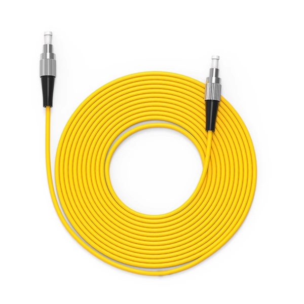
In this video, Joe would display how to connect SC fiber optical connector in 2 minutes. Related product:. Step 4 i s to affix the fiber to the connector. The fiber should be inserted into the connector until it is flush with the ferrule end. Step 5: Let the epoxy cure. These connectors ensure high-quality signal transmission, which is essential for reliable internet and communication services. SC APC connectors offer superior optical. There are many types of fiber optic connectors, including SC, LC, FC, ST, D4, MU, MT/MPO, etc. These connectors can be divided into single-mode and multi-mode fiber optic connectors according to their structure and purpose. To learn more about the types of fiber optic connectors, click here: Types. The global SC fiber optic connector market is valued at approximately 903 million USD in 2025 and is projected to grow steadily, which reflects its continuing role as a standard interface in fiber infrastructure, including plant backbones and industrial automation links, according to SC connector. SC fiber connectors, or Subscriber Connectors, are widely used in telecom and networking for their strong performance and easy handling. They're known for a secure push-pull connection that's quick to insert and remove.
[PDF]

It transforms high volumes of electrical signals into optical signals for transmission over fiber cables, or reverses the process at the receiving end. Think of it like a Type-C to USB adapter in everyday tech—its core function is seamless conversion between electrical and optical. Optical modules are compact devices that convert electrical signals into optical signals and vice versa. They are used in fiber optic communication systems to transmit data over long distances with minimal loss and interference. These modules typically consist of a laser or LED transmitter, a. In the world of fiber optic communications, optical transceiver modules play a pivotal role as interfaces that convert electrical signals to optical signals and vice versa. An optical module works at the physical layer of the OSI model and is one of the core components in the fiber communication. The frequency response characterization of these electrical-to-optical (E/O, modulators sometimes integrated with lasers) and optical-to-electrical (O/E, photo detectors and receivers) converters can be important in terms of such parameters as bandwidth, flatness, phase linearity and group delay. The optical module serves as a crucial component in optical fiber communication systems, operating at the physical layer, which is the lowest layer in the OSI model. Among various optical module form factors, SFP (Small Form-Factor Pluggable).
[PDF]
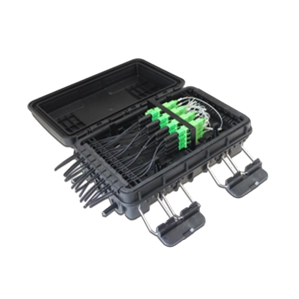
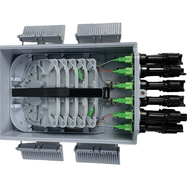
Learn how to splice 4-fiber optic cables using ODF in this complete step-by-step tutorial. Whether you are a beginner or a professional in fiber optic networking, this guide will help you splice fiber cables accurately, manage connections with ODF panels, and ensure. This complete guide explores everything you need to know about ODFs — from their structure, types, and key components, to installation best practices and modern design trends. Whether you're building a central office, data center, or FTTx distribution network, understanding the right ODF. How to Splice 4-Fiber Optic Cable with ODF | Step-by-Step Fiber Optic Splicing Tutorial. This guide demystifies ODF, exploring their design, core functions, types, and how they. An Optical Distribution Frame (ODF) is the central hub for fiber splicing, termination, patching, and cable protection in modern optical networks. It's where incoming and outgoing cables meet. It does four key things: Think of it as the central hub for your fiber network. Without it, cables get tangled. This article explores the types, components, applications, installation, and maintenance best practices, providing a.
[PDF]

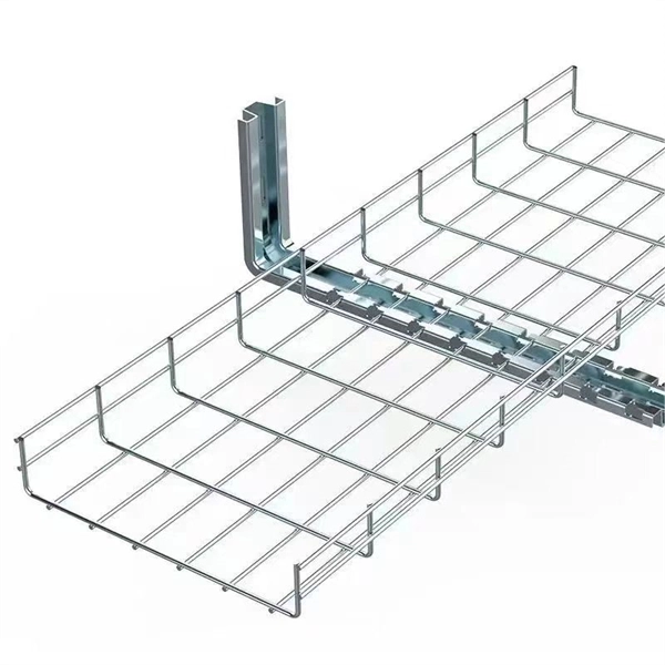
This guide covers the critical steps, from selecting the right electrical cable tray and performing accurate cable fill calculations to managing a safe cable pull through and ensuring all bonding and grounding requirements are met. Article Summary: A compliant cable tray installation requires a thorough understanding of NEC Article 392, proper structural support, and precise installation techniques. Structural building members should never be cut, and cable trays should not be installed in hoist ways or where subject to physical damage. Cable tray systems re to be installed so that they are accessible. Here is a step-by-step guide on how to install a standard metal cable tray system (e., ladder or perforated type). But before you lay the first tray or clamp down a single cable, you need a solid plan. When ofloading tray from a flat deck trailer using an overhead crane, care should be exercised in the placement and length of the slings to prevent crushing the product (siderails). Only ofload. Cable tray systems are designed for easy installation and to accommodate power, communications, and signal cabling across a variety of applications. When properly installed, cable trays prevent damage to cabling and the area's structural integrity. When installed and engineered properly, cable.
[PDF]

In this article, you will learn the step-by-step process of testing your solar panels using a multimeter. We will cover the essential tools you need, the specific measurements to take, and how to interpret the results. A $15 multimeter and 5 minutes of testing can diagnose most solar panel problems. Measure Voc (open circuit voltage) — if it reads 0V, the panel or wiring is dead. If it reads 60–80 % of rated, a bypass diode has failed. By the end of this guide, you will be equipped with the knowledge to diagnose. Learning how to test solar panel with multimeter is useful for homeowners, technicians, farmers, and anyone using solar energy systems. A digital multimeter allows you to check voltage, current, continuity, and resistance. Fluke recommends using the Fluke 117 Electrician's Multimeter or Fluke 283 FC CAT III 1500 V Digital Multimeter to test solar modules. Here's how a technician tests solar modules with a multimeter:. A multimeter is an indispensable tool for anyone working with solar panels, allowing for accurate measurements and diagnostics. It empowers users to assess the performance, identify faults, and ensure optimal energy production. Perfect for DIY solar builders, RV owners, o. more Audio tracks for some languages.
[PDF]
Unlike, single-mode fiber does not exhibit. This is due to the fiber having such a small cross section that only the first mode is transported. Single-mode fibers are therefore better at retaining the fidelity of each light pulse over longer distances than multi-mode fibers. For these reasons, single-mode fibers can have a higher than multi-mode fibers. Equipment for single-mod.
[PDF]
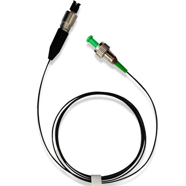
In this informative guide, we'll walk you through the step-by-step process of stripping and preparing fibre optic cable for termination, covering techniques, tools, and best practices to help you achieve successful terminations in your fibre optic installations. Strip the jacket and buffer: Using a fiber optic cable stripper, remove the outer jacket and buffer tubes from the cable. Make sure to strip the appropriate length, as specified by the manufacturer. Be cautious not to damage the fibers during this process. Cleave and cut the fibers: After. In this instructional video, Bob Licari, Test Equipment Product Manager, demonstrates a simple way to strip optical fiber. more Audio tracks for some languages were automatically generated. Eventually, this imperfection can initiate a crack when the. It is impossible to work in fiber optics without having a good working knowledge about cables and skills in pulling, placing and preparing cables for termination and splicing. Properly stripping the cable and preparing the fibre ends ensures a clean and secure connection, leading to optimal signal transmission and network performance. Terminating fiber optic cables essentially means putting connectors on fiber optic cable so that you can connect the cable to various devices or network components. Think of it as the equivalent of connecting the dots in a complex puzzle; without proper termination, the whole system can break down.
[PDF]

The setting value can be finely adjusted manually. Press and hold the and buttons simultaneously for three seconds. Use the to select "rSt", then press the button. Settings are summarized in "Basic" and "Advanced" categories. Providing quick solutions for every scenario. In cases where more advanced features or troubleshooting is necessary, the "Advanced". This video covers how to setup and configure the Wenglor OPT2041 Fiber Optic Sensor from AutomationDirect. **Please check our website for our most up-to-date product pricing and availability. This sensor works with both Plastic and Glass fibers. Keep in mind that the color and reflectivity of the. The KEYENCE FS-N10 Fiber Sensor is a versatile and reliable device used for detecting objects. This sensor uses a fiber optic cable to transmit and receive light, allowing for accurate and precise detection in a variety of applications. The FS-N10 series is capable of detecting objects of different. Fiber optic Sensors; How to program Keyence Fiber optics amplifier from EMI Documentation can be found here:. This is the SET push button; this is used to calibrate the sensitivity.
[PDF]

These numerical codes, ranging from 1 to 99, uniquely identify the functions of protective relays, associated devices, and control equipment in electrical power systems. In electric power systems and industrial automation, ANSI Device Numbers can be used to identify equipment and devices in a system such as relays, circuit breakers, or instruments. The device numbers are enumerated in ANSI / IEEE Standard C37. 2 Standard for Electrical Power System Device Function. According to the ANSI/IEEE standards, device function numbers are crucial identifiers in power system protection and control engineering. ANSI IEEE Standard Device Numbers are below: (the more commonly used ones are in bold) 86T is a Lockout Relay for a. The widely used United Sates standard ANSI/IEEE C37. Even in those parts of the world where IEC standards are predominate, the use of ANSI numbering. For power grid systems, ANSI and IEEE functional number codes dictate the use and restrictions of both the devices themselves, as well as the functions of those devices within the scope of a circuit. These devices include switches, disconnects, circuit breakers, generators, and motors. Instead of verbal descriptions, we use numbers to describe the functions of a relay. Why use numbers instead of words? Efficiency.
[PDF]

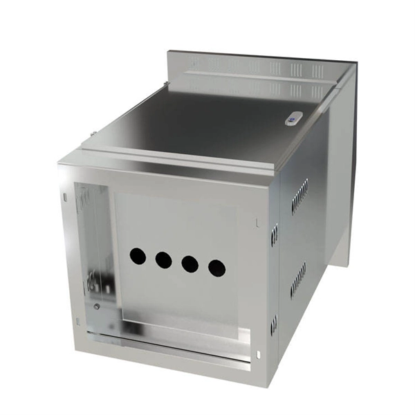
This guide shows you how to organize circuit breaker wiring properly. You will learn to build a safe, efficient, and professional electrical system today. Circuit breaker wiring configurations involve organizing main switches, busbars, and branch breakers within a distribution box. While some homeowners may attempt this, it's highly recommended to hire a qualified, licensed electrician for circuit breaker box wiring. This is a complex and potentially dangerous task that involves working with high voltage electricity. Mistakes can lead to serious injury, fire, or damage to. A breaker box, also known as a circuit breaker panel, is an essential component of any electrical system. It is responsible for distributing electricity throughout a building, ensuring that each circuit receives the proper amount of power. To understand how a breaker box works, it is helpful to. When installing or troubleshooting a power distribution system, understanding how to correctly connect the main electrical supply to the control panel is crucial. The first step involves running a dedicated cable from the incoming supply to the distribution panel, ensuring it is rated for the load. How to read these diagrams. This page contains wiring diagrams for a service panel breaker box and circuit breakers including: 15amp, 20amp, 30amp, and 50amp as well as a GFCI breaker and an isolated ground circuit. Messy distribution boxes are dangerous and very hard to fix.
[PDF]