In this video we will learn how to configure cisco core switch active active using HSRP step by step. In this LAB we practice on creating vlan, distribute vlan to other switch in our network, creating interface vlan and assign IP address for layer 3 routing. Follow these simple best practices to set up a new network switch. Just like riding a bicycle, nobody's born knowing how to setup a network switch. And this process is a little more advanced than, say, setting up your home Internet or even a plug-and-play type switch. But, with the right guidance. Looking to configure a Cisco switch for the first time? If the answer is YES, you're in the right place. You're going to configure: SSH access with local AAA authentication. Here's a network diagram, so you can follow. When you deploy a new switch, it's important to configure it properly to ensure optimal performance, security, and functionality. It comes with an IOS. An IOS is a Cisco proprietary operating system. It allows you to configure, customize, and use Cisco devices as needed. It includes thousands of commands for various tasks. This tutorial explains essential. Although a Cisco switch is a much simpler network device compared with other devices (such as routers and firewalls for example), many people have difficulties to configure a Cisco Catalyst Switch. Configuring a Cisco switch is a fundamental task for network administrators, as it lays the groundwork for.
[PDF]
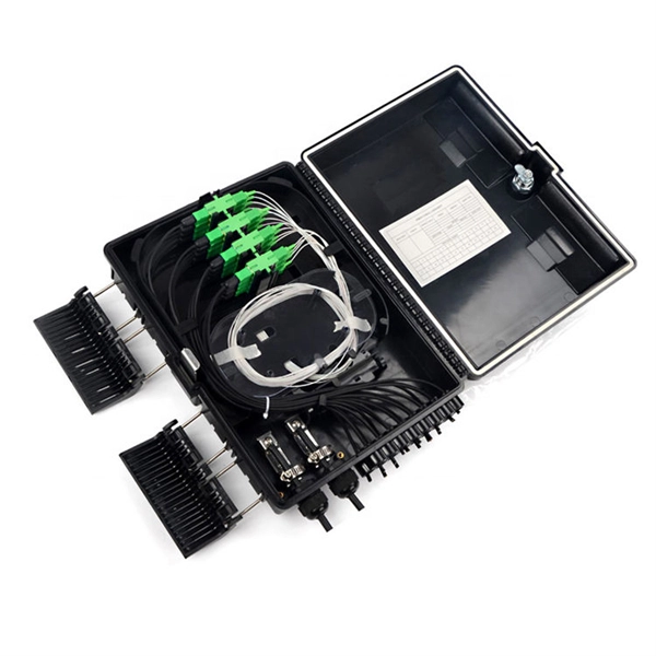
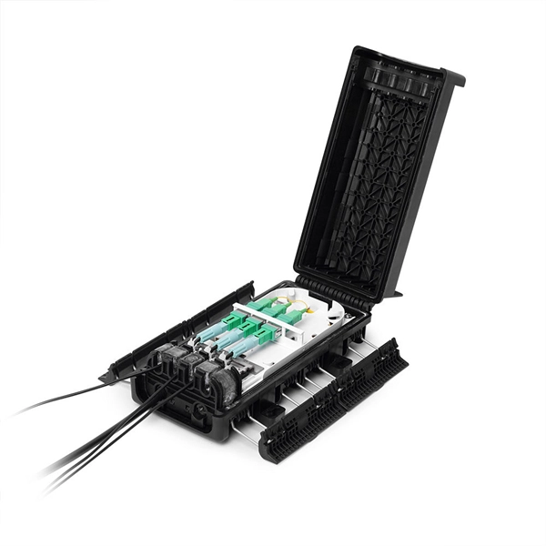
6 core Fiber Optical Splicing With 24 Port LIU || Full Installation || Beginner Watch this video Fiber optic splicing is the process of joining two fiber optic cables together to create a conti. more. In this article, we'll explain how to connect multiple Ethernet switches using fiber optic cables and the equipment required for this to work. Network topology refers to the way in which the links and nodes of a network are arranged in relation to each other. Simply put, it defines how network. Choose an SFP module based on the fiber optic cabling that will be connected to the network switches. SFP transceiver modules almost always require two fiber optic cable strands. Most modern SFP transceiver modules. Most modern fiber-enabled network switches require an SFP transceiver module featuring a duplex (two strand) multimode OM3 or duplex single mode OS2 connection with LC connectors. Direct attach cables with pre-terminated SFP connections may also be used. Download the Application PDF SFP transceiver. This article will guide you through the necessary tools, materials, and methods on how to connect fiber optic cables effectively, ensuring you achieve optimal performance from your fiber optic network. These diagrams help engineers plan infrastructure for residential and commercial buildings. By using light signals, fiber optics provide faster speeds and better reliability than.
[PDF]

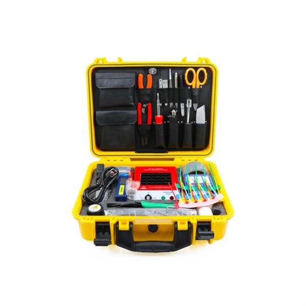
When it comes to testing fiber optic cables, a Visual Fault Locator (VFL) is an essential tool in your toolkit. A VFL is used to detect faults, breaks, or bends in fiber optic cables by emitting a bright red light that is visible even through the fiber's jacket. Let's dive into everything you need to know about mastering VFLs. It's a cost-effective and. Visual Fault Locator (VFL) testing is one of the most fundamental inspection methods used in FTTH, ODN, and data center environments. A VFL emits a visible red laser (typically 650 nm) that travels along the fiber core and leaks out at points of excessive loss, fiber breaks, or microbends. Although. The Fiber Visual Fault Locator Kit is an essential tool for network technicians and engineers; it provides an accurate and quick method of finding such problems as breaks, bends or faults that may affect the network's operation. It works by injecting a visible red laser light (usually in the 650nm wavelength) into the fiber. When the light encounters a fault, such as a break, bend, or bad splice, it leaks out of the fiber, making the. Conducting efficient, repeatable fiber optic cable certification requires an array of specialized test equipment: Optical Loss Test Set (OLTS) – Integrates adjustable light source and power meter for efficient, Tier-1 insertion loss testing. Visual Fault Locators – Handheld devices projecting.
[PDF]

Make sure you're near your router. Select the gearwheel icon at the bottom right of the home screen. Select 'Internet' and then 'Internet Settings'. Your Nintendo Switch is now wirelessly connected to the internet. Steps to manually create an Internet connection on a Nintendo Switch console. The following process is generally only necessary for more technical users with unique networks that require they configure devices to connect to their network. Users with a standard wireless network can follow a more. In this comprehensive tutorial, we guide you through the process of setting up internet connectivity on your Nintendo Switch, including the original model, Switch OLED, and Switch Lite. Whether you prefer a Wi-Fi connection or a wired setup, our step-by-step instructions will ensure you can. Your. Follow this step-by-step guide to switch your internet service provider. Enter your zip code below to see all available internet providers in your area. Determine what internet you want What made you Google “how to change my. When attempting to connect your console to the router, gateway or modem, you need to use a long network cable (This should come with your Nintendo Switch, but in case it doesn't, you would require an ethernet cable). Prerequisites Before we dive into the steps, make sure you have the following: Step 1: Setting Up Your Console To connect your Nintendo Switch to the internet, you'll need to set it up first.
[PDF]
The detailed steps outlined herein provide a comprehensive understanding of optical attenuator installation and adjustment. Proper execution enhances the efficiency and stability of the attenuators and the overall communication system. Fibre optic attenuators, also called optical attenuators, are passive devices used to reduce the power level of an optical signal. Assemble all necessary tools and equipment, such as a fiber cleaver, fusion splicer, optical power meter, and connector cleaning tools. These are the cornerstones of a seamless installation. Equally. Having a deep understanding of how to select a fiber optic attenuator, regardless of the type—fixed or variable—and the type of fiber and connector is critical to the durability and maintainability of a reliable network. Taking optical power measurements before installation of a fiber optic. Optical Signal Attenuation is the single greatest factor limiting the distance and performance of your network. Understanding it is crucial for anyone involved in data centers, telecommunications, or enterprise networking. In this. 📦 For purchasing, use the RP Photonics Buyer's Guide for optical attenuators. It provides an expert-curated supplier directory, buyer-focused technical background information, and structured selection criteria to support professional procurement decisions. Optical attenuators are devices that.
[PDF]

When it comes to testing fiber optic cables, a Visual Fault Locator (VFL) is an essential tool in your toolkit. A VFL is used to detect faults, breaks, or bends in fiber optic cables by emitting a bright red light that is visible even through the fiber's jacket. It's a cost-effective and. A Visual Fault Locator which can be also called visual fault identifier (VFI), fiber fault locator, fiber fault detector, etc., is a visible red laser light designed to inject visible red light energy into an optical fiber. Using a VFL to diagnose issues can save time and cost when diagnosing an. A visual fault locator is a compact, handheld device that emits a visible light beam, typically in the red wavelength range, through a fiber optic cable. It works by injecting a visible red laser light into the fiber, which can be seen through the jacket or at the end of the cable. If the light doesn't come out the other side, there might be a problem. You. And in the end we will show you how to use an old cell phone's camera to detect light in a fiber optic system. It uses a bright incandescent bulb or visible LED source to.
[PDF]
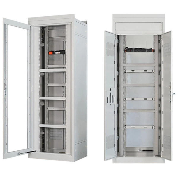
These aggregation switches typically operate at Layer 2 or Layer 3 of the OSI model, depending on the network topology and configuration requirements. The three layers of a traditional three-layer network design are the core layer, aggregation layer, and access layer. As the physical part of the aggregation layer, aggregation switches typically play a. An aggregation switch consolidates data traffic from multiple network access switches into a single high-bandwidth link directed toward a core network or data center. It is essential for larger networks requiring efficient data flow. They function as gateways to collect routing information in a point of delivery. Most medium-to-large networks follow a three-tier hierarchy: access, aggregation (sometimes called distribution), and core. Each tier has a distinct job. Access switches are the ones closest to end users and devices. They sit in wiring closets or on top of server racks, providing ports for.
[PDF]
S-polarized light is reflected at a 90 degree angle with maximum efficiency of >90%. A beam splitter or beamsplitter is an optical device that splits a beam of light into a transmitted and a reflected beam. It is a crucial part of many optical experimental and measurement systems, such as interferometers, also finding widespread application in fibre optic telecommunications. In its. 📦 For purchasing, use the RP Photonics Buyer's Guide for beam splitters. It provides an expert-curated supplier directory, buyer-focused technical background information, and structured selection criteria to support professional procurement decisions. The beams splitter consists of a pair of precision high tolerance right angle prisms cemented together with a dielectric coating on the hypotenuse. Multi-wavelength beam splitters can be optimised for different ratios of reflected and transmitted light. Thanks to a special coating, the reflectance remains stable for every polarization direction. It is possible to achieve reflectance values of 0. Light from an input fiber is first collimated, then sent through a beam splitting optic to divide it into two. The resultant output beams are then focused back into the output fibers. Both 1XN and 2XN.
[PDF]

It operates by emitting a bright and visible red laser light into the fiber and detecting the location of faults by observing the light leaking out of the fiber. It is also possible to locate faults in OTDR dead zones and perform fiber identification from one end to the other. When it comes to testing fiber optic cables, a Visual Fault Locator (VFL) is an essential tool in your toolkit. It's a cost-effective and. Whether you're a seasoned technician or a fiber enthusiast, a VFL is the first step to make your life easier in troubleshooting a fiber optic cabling issue. We will be explaining what The VFL's primary purpose is, and how best to use it. Below are some key use cases for a VFL. It gives instant visual proof of where light escapes the fiber. Even beginners can spot bends, cracks, or bad splices without complex tools. A visual fault locator saves time, cuts stress, and reduces repeat work., optical fiber fault detector, optical fiber fault test pen) is a 650nm (± 20nm) semiconductor laser as a light-emitting device, which emits stable red light through a constant current source drive, and connects with the optical interface into the optical fiber, so. In the world of fiber optic communication, diagnosing and troubleshooting network issues is essential to maintain smooth connectivity. Whether you are a beginner or a professional working with fiber optics.
[PDF]

The setting value can be finely adjusted manually. Press and hold the and buttons simultaneously for three seconds. Use the to select "rSt", then press the button. Settings are summarized in "Basic" and "Advanced" categories. Providing quick solutions for every scenario. In cases where more advanced features or troubleshooting is necessary, the "Advanced". This video covers how to setup and configure the Wenglor OPT2041 Fiber Optic Sensor from AutomationDirect. **Please check our website for our most up-to-date product pricing and availability. This sensor works with both Plastic and Glass fibers. Keep in mind that the color and reflectivity of the. The KEYENCE FS-N10 Fiber Sensor is a versatile and reliable device used for detecting objects. This sensor uses a fiber optic cable to transmit and receive light, allowing for accurate and precise detection in a variety of applications. The FS-N10 series is capable of detecting objects of different. Fiber optic Sensors; How to program Keyence Fiber optics amplifier from EMI Documentation can be found here:. This is the SET push button; this is used to calibrate the sensitivity.
[PDF]

This article provides a comprehensive guide on how to capture network packets on a switched network using Wireshark, covering key concepts such as port mirroring, network tapping, and other methods to ensure you can monitor traffic effectively on a switched network. Packet capture is supported on the Cisco Catalyst 9300 Series Switches. The following sections provide information about the prerequisites for configuring packet capture. Before starting a Wireshark capture process, ensure that CPU. Embedded Packet Capture (EPC) is an embedded system management tool used for tracking and troubleshooting network packets. This tool helps network administrators capture packets entering and leaving Cisco devices. EPC can be used with Access Control Lists (ACLs) to filter specific packets based on. Packet capture and packet analysis are made possible by the multi-step packet capture protocol (PCAP), which makes use of many tools. Packet sniffers are tools used to do packet capture; they are the first step in the process. They are. Of course switches work on an entirely different principle and do not replicate unicast packets out of every port on the switch, but keep them isolated unless it's a broadcast or multicast. In traditional hub-based. This enables us to easily take captures directly from the switch and export them for analysis. The process is very straightforward and only takes a couple of minutes to set it up. The packets are then stored.
[PDF]
Set your fiber optic-to-Ethernet converter box in a location near your Ethernet switch and plug in its power adapter. Insert the end of your fiber optic network line into the fiber optic connector on the converter box. Fiber optic cabling is increasingly used to connect network switches and other datacom equipment, especially in long-distance and mission-critical applications. Fiber provides: Increased internet signal bandwidth. Most modern fiber-enabled network switches require an SFP transceiver module. This is a cost-effective and high performance way to connect network switches. Advantages Determine the length of the fiber run and choose either multi mode for runs under 1000 feet or single mode for runs over 1000 feet. SFP transceiver modules are specific to the type of fiber being connected. Connecting a switch to a fiber optic network involves several steps and requires specific equipment to ensure a successful and efficient connection. This guide will. In this article, we'll explain how to connect multiple Ethernet switches using fiber optic cables and the equipment required for this to work. Network topology refers to the way in which the links and nodes of a network are arranged in relation to each other. Ethernet ports are designed for copper cables (like Cat5e or Cat6), which transmit data using electrical signals. You need a media converter or a.
[PDF]

There are two ports on the left side of the switches reserved for functions outside of communicating with the node and storage array. The ports are labeled: the serial port used to configure the switch. The Cisco MDS 9148S switch provides the following types of ports: Console port (Interface Module)—An RS-232 port that you can use to create a local management connection. MGMT 10/100 Ethernet port (Interface Module)—An Ethernet port that you can use to access and manage the switch by IP address. A vertical line, called a pipe, indicates a choice within a set of keywords or arguments. [x | y] Optional alternative keywords are grouped in brackets and separated by vertical bars. Cisco Catalyst 9500. These are located on U28 and U27 respectively. This fiber switch utilizes OEO Technology. The Primary Remote Control is an RJ45 port that is 10/100 Base-T Ethernet and is IP addressable. Access either of two LC Duplex Fiber Optic Networks from one computer connected. The switch is typically grounded during installation and provides an ESD port to which you can connect your wrist strap. Do not remove and insert a transceiver more often than is necessary. One of the Ethernet ports can also be used to export analytic.
[PDF]