The optical power meter is similar to the voltohmmeter in application but measures the optical resistance (losses measured in dBm or dBM) of a cable before and after installation and provides a comparative analysis of the splices. The range of the meter is adjustable. Regularly testing fiber optic cables helps minimize network downtime, lengthens the network's longevity, reduces maintenance requirements, and helps support network reconfiguration and upgrades. These factors significantly add to the fiber optic network's long-term performance, manageability, and. Several types of tests are commonly conducted to assess and maintain the health of fiber optic networks. Continuity testing verifies that the fiber is intact and that light can pass through from one end to the other without any blockages. These test procedures assess the physical and functional qualities of fiber optic cables, connectors, and the network as a whole. Key tests include: Effective fiber testing utilizes advanced tools such as Optical. One way to test a splice is to use an Optical Power Meter. As the components like fiber, connectors, splices, LED or laser sources, detectors and receivers are being developed, testing confirms their performance specifications and helps. Regular testing of fiber optic cables is not just a preventive measure; it's an investment in the longevity and efficiency of your network. By identifying potential issues early, you can enhance.
[PDF]
SFP transceivers are available with a variety of transmitter and receiver specifications, allowing users to select the appropriate transceiver for each link to provide the required optical or electrical reach over the available media type (e.g. or copper cables, or cables). Transceivers are also designated by their transmission speed. SFP modules are commonly available in se.
[PDF]
The QSFP28 optical transceiver module is designed for use in 100GBASE Ethernet throughput up to 100km over single mode fiber (SMF) using a wavelength of 1310nm via duplex LC connectors. The 100 Gigabit Ethernet signal is carried over four wavelengths multiplexing and demultiplexing of the four. 100G ZR4+ optical module provides up to 103. 12Gbps data rate using QSFP28 footprint at the wavelengths of LWDM, which is designed with digital diagnostic monitoring. All Rights Reserved. GigOptics is a leading supplier of Optical Transceivers in the USA. We offer a wide range of products at great prices with fantastic service (SFP, SFP+, SFP28, QSFP+, QSFP28, XFP, etc. Various Switch Tests: Each module is quality tested for compatibility in the multi-brand switches. Comprehensive Testing: Each. The 100GBASE-ZR4+ QSFP28 delivers 100 km reach over single-mode fiber without external amplification. With a 34 dB link budget (FEC enabled) and integrated SOA receiver, this is the longest-reach 100G option in the QSFP28 form factor. 4 LAN WDM lanes at 103.
[PDF]

Nigeria Sfp Optical Module Suppliers Directory provides list of Nigeria Sfp Optical Module Suppliers & Exporters who wanted to export sfp optical module from Nigeria. Don't know your target market? Wanted to market your Sfp . The Cisco SFP 10G SR module is meant to provide data transfer at 10Gbps speed with short-range. Qsfp-100g-sr4-s 100g sfp module s-class qsfp-100g-sr4-s 100gbase sr4 qsfp transceiver, mpo, 100m. Small Form-factor Pluggable (SFP) is a compact, hot-pluggable network interface module format used. The best choice is Cisco SFP Transceivers are the best in offering high performance and flexibility in the enterprise and data center networking. The hot-swap modules offer speeds of 1G, 10G, 25G, 40G, and 100G and will smoothly scale to various networking requirements. They come in SFP+, SFP. Fiber optic transceivers are widely used in telecommunication, CATV, FTTx, and various kinds of other data communications. Their commitment to high-quality service and tailored recommendations can support organizations looking to enhance their digital operations. Do You Really Know Where Your Transceivers Come From? Factory-direct optical transceivers and high-speed cables, from legacy links to 1. 6T, built to deploy faster, scale cleaner, and stay compatible as your network evolves. At scale, the biggest problems come from what you don't control, not what.
[PDF]

A 630A MCCB means the breaker is rated to handle up to 630 amperes of continuous current without tripping under normal conditions. This type of MCCB is commonly used in industrial power distribution panels, commercial buildings, and large electrical systems where higher current. A Molded Case Circuit Breaker (MCCB) is a protective device designed to automatically disconnect electrical circuits during overloads or short circuits. This type of. This ComPacT NSX630N is a complete 3P 3d fixed circuit breaker designed to optimize space and breaking capacity. It is an optimal choice for all standard and specific applications. The breaking capacity (Icu) is 50kA rms at 415VAC 50/60Hz. This product. Fuji Molded Case Circuit Breakers are more compact (especially 100A, 125A, 250A frames) than any breakers on the market, so they take up less space in control panels. U denotes non-interchangeable trip unit. With a 630A frame rating and adjustable settings from 400A to 630A, it offers flexible protection for high-power applications. Ir = 300 - 630A; Icu = Ics = 65kA at AC 440V How to request a quotation How can I request a quotation for more than one product? (Watchlist). GENLITEC POWER® GTS630 630A Automatic Transfer Switch (ATS) Panel is designed for seamless and automatic power switching between the main utility supply and backup generators. Engineered for high-power applications, this ATS ensures uninterrupted power supply, reducing downtime and enhancing.
[PDF]
An optical module is a typically hot-pluggable optical transceiver used in high-bandwidth data communications applications. Optical modules typically have an electrical interface on the side that connects to the inside of the system and an optical interface on the side that connects to the outside world through a fiber optic cable. The form factor and electrical interface are often specified by an interested group using a (MSA). Optical modules can either plug into a front pa.
[PDF]

Instructional video on how to assemble your full-beam log splitter of 25-37 tons. championpowerequipment. comParts Store: https://shop. This manual contains important safety precautions which should be read and understood before operating the product. Failure to do so could result in serious injury. Specifications, descriptions and illustrations in this manual are as accurate as known at. se of a Champion Power Equipment (CPE) product. CPE designs, builds, and supports all of our p oducts to strict specifications and guidelines. With proper product knowledge, safe use, and regular maintenance, this p gers and maintenance of the product before use. Fully familiarize yourself, and. DO NOT operate the log splitter inside any building, including garages, basements, crawlspaces, sheds, or enclosure. DO NOT allow exhaust fumes to enter a confined area through windows, doors, vents or other openings. Using an engine indoors CAN KILL YOU IN MINUTES. Quick-disconnect cordsets allow sensor, lighting and safety devices to be replaced or moved quickly and are available in both single- and double-ended models. For added versatility or challenging applications, splitters, cables, and field wireable connectors are available to complete your system.
[PDF]
We offer a wide range of OEM-compatible optical transceivers & cables, ensuring reliable, high-speed connectivity. The transceiver consists of three sections: a Cooled EML laser transmitter, a APD photodiode integrated with a trans-impedance preamplifier (TIA). As a professional optical transceiver manufacturer, Innoptical offers an extensive assortment of optical transceivers to fit your requirements. Ranging from low-data rate to 800 GB, our transceivers cover types of SFP, SFP+, SFP28, SFP56, QSFP+, QSFP28, QSFP56, QSFP-DD, OSFP, GPON OLT transceivers. Product Specifications/Features SFP Optical Transceivers are hot-swappable, compact media connectors that provide instant fiber connectivity for your networking gear. They are a cost effective way. The optical transceiver is designed for use in 100/155Mbit/s data links. It provides the SC. The LS-SM312G-40C SFP transceivers are high performance, cost effective modules supporting data rate of 2. 5Gbps and 40km transmission distance with SMF. By seamlessly integrating advanced silicon photonics, ultra high speed circuit and packaging designs, Hyper Photonix offers a comprehensive range. Through lean management, manufacturing and our Source Lean Quality (SLQ) system, we run our world-class operation at maximum efficiency, identifying and eliminating waste in our processes to create more value for our customers. Our technical expertise in R&D runs deep with manufacturing process.
[PDF]

JIAXUN JQ-LW100-ER4C QSFP28 Optical Transceiver Module is designed for use in 100GBASE Ethernet throughput up to 40km over single mode fiber (SMF) using a wavelength of 1310nm via duplex LC connectors. And This transceiver is compliant with IEEE 802. 3ba 100GBASE-LR4 and IEEE 802. 3bm. Topstar is a leading optical modules manufacturer and optical solutions provider. We are dedicated to helping you build, connect, protect and optimize your network. Topstar focuses on R&D and has our Top-trans” brand SFP/SFP+/XFP+QSFP/CFP/QSFP28 series of modules, we offer 24*7 hours online service. Here are the top-ranked sfp module companies as of May, 2026: 1. EnGenius Technologies, 2. What Is a SFP Module? What Is an SFP Module? SFP (small form-factor pluggable) modules are optical transceivers that convert electrical signals into optical signals. Founded in 2008, it has grown to become one of the largest optics manufacturers in the world. According to the YOLE statistics, InnoLight's share of the optics transceiver market is 11%. 3bm CAUI-4. Exhausted from looking for a reliable compatible SFP manufacturer? This post offers quick access to the SFP module price list by researching top vendors. SFP modules have been in large demand in data centers with the continuous development of optical communication. OEM firmware updates silently break.
[PDF]
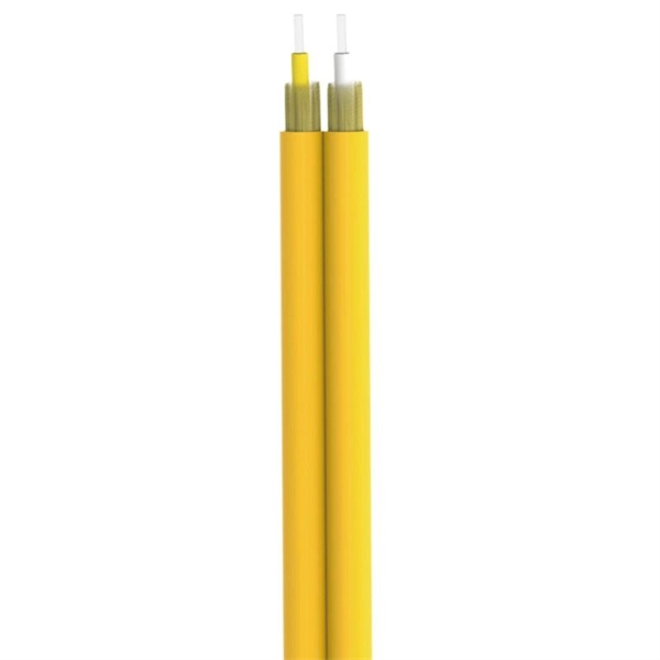
These installation instructions provide overview and specification information for small form-factor pluggable (SFP/ SFP+/SFP28) modules, as well as instructions for installing and removing the modules. SFP (Small Form-factor Pluggable) transceivers are essential components in modern fiber optic networks, enabling network devices such as switches, routers, and servers to transmit and receive data over optical fiber. By converting electrical signals into optical signals—and vice versa—SFP. Gigabit single-mode fiber optic module Common parameters of optical modules 1. Center wavelength 1) 850nm (MM, multi-mode, low cost, but short transmission distance, usually only 500M); 2) 1310nm (SM, single mode, large loss during transmission, small dispersion, generally used for transmission. As a leading provider of fiber optic solutions, Weunion offers a wide range of SFP-compatible products, including optical transceivers, DAC/AOC cables, LC patch cords, and MPO/MTP assemblies. While they may appear to be simple plug-in transceivers, SFP modules are precision-engineered devices that directly influence network. o In optical modules, "core" refers to the light-transmitting channel in the fiber. A 1-core module uses a single fiber core for data transmission, while a 2-core module uses two cores. o Think of a highway. A 1-core fiber is like a single-lane road—only one car (or data signal) can travel at a.
[PDF]
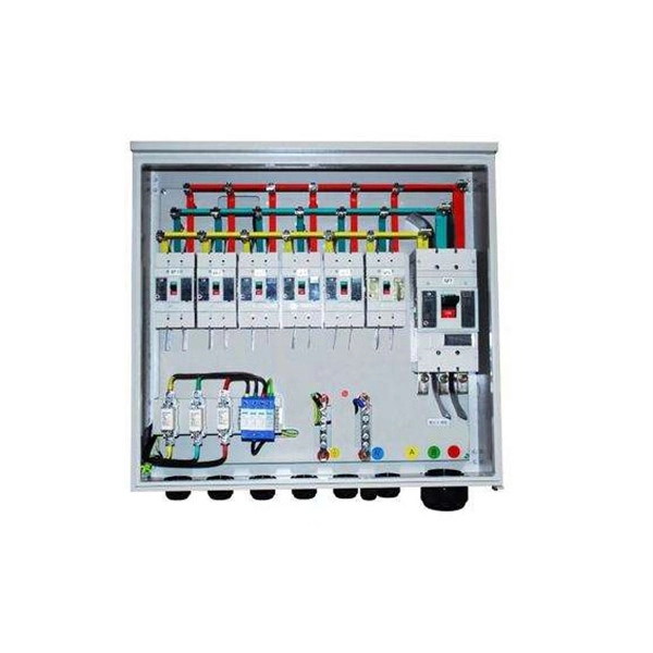
In this video, we'll walk you through the process of wiring a home distribution box with a detailed connection diagram. Whether you're an electrician or a DIY enthusiast, this guide will help you understand the basics of home electrical distribution. more Welcome to our channel! In this video. This guide provides step-by-step instructions for connecting a distribution box and highlights key factors to consider during installation. What Is a Distribution Box? A distribution box, also known as an electrical distribution board, is a critical component in electrical systems. It has three categories: residential, commercial and industrial electrical distribution boxes, all of which play important roles in their respective electrical. Understanding how to safely set up the main connections of a home's power distribution system is essential for ensuring reliable and secure operation. A correct installation process minimizes the risk of electrical faults and increases the longevity of your setup. It is usually equipped with circuit breakers, fuses, terminal connectors, and other components. It serves as a central hub for distributing electricity throughout a building, ensuring that power is delivered safely and efficiently to all the required locations.
[PDF]
Online catalog w/end user & wholesale pric. Online catalog w/end user & wholesale pric. Check each product page for other buying options. Shop products from small business brands sold in Amazon's store. Learn more Need help?. What's the price range for Telephone Cords? The average price for Telephone Cords ranges from $10 to $900. Price when purchased online BUTTERFLY- Softalk 25' Phone Handset Cord Black Coiled, 4P4C Rj9 High Quality New Shipped!. Shop for Telephone Handset Cords at Walmart. Live better. 25 Ft., white, modular line cord, allows phone to extend 25 Ft. from wall, modular plugs at both ends and is compatible with 2 or 4 wire systems. Make a good call by choosing the Power Gear 100ft. line cord and replace your old, worn-out or damaged cord with a high-quality upgrade. Find the items you need to hook up your landline phone.
[PDF]
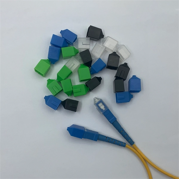
They directly point to the module type. Additionally, observing the color of the optical module's pull tab is a straightforward way to check it. Multimode: Pull tabs are typically black. Another very direct method is checking the. How to distinguish whether an optical fiber module is single-mode or multi-mode? Optical modules are core photoelectric conversion components in fiber-optic communication, data centers, enterprise networks, and telecom transmission systems. Correctly distinguishing single-mode and multi-mode. Understanding whether your SFP module is single-mode or multimode is crucial in network design. The choice impacts the transmission distance, data rate, and cost of your setup. Typically, single mode SFP modules are labeled as "SM" or "single mode," while multimode modules may be labeled as "MM" or "multimode. ". To determine whether the SFP module in your hand is single-mode or multi-mode, the most straightforward method is to check the color of the pull ring, for example, blue pull rings and red pull rings are single mode, and black pull rings are multimode. Multimode (MMF) SFP modules involves a cross-referencing protocol of physical bail colors, EEPROM telemetry, and wavelength specifications. Precise verification prevents "Ghost Links" and Mode Field Diameter (MFD) mismatches that degrade 800G AI fabric performance.
[PDF]