Long Expansion Cycle: Optical fiber preform production has high technological barriers, and the expansion cycle can take as long as 18-24 months. Even if manufacturers start expanding immediately, the new capacity will not be available until at least 2027. This phenomenon is the result of multiple factors, including tight supply of optical fiber preforms (preforms), long expansion cycles for optical fiber production capacity, and the explosive growth of emerging applications such as AI computing power and drones. The expansion cycle of optical fibers is generally less than 6 months, and fiber optic cables can take 3 months. The expansion of production requires the purchase of equipment and the construction of factories. At the heart of this transformation lies fiber optic cable manufacturing, a precise and sophisticated process that powers our interconnected world. With the global fiber optic market reaching $6 billion and growing at 10% annually, the need for high-quality manufacturing solutions has never been. The manufacturing process of fiber optic cables involves several intricate steps that culminate in the production of high-performance data transmission solutions. This process begins with the creation of a preform, which serves as the foundation for the optical fibers within the cable. This intricate process combines cutting-edge technology, precise engineering, and.
[PDF]

It transforms high volumes of electrical signals into optical signals for transmission over fiber cables, or reverses the process at the receiving end. Think of it like a Type-C to USB adapter in everyday tech—its core function is seamless conversion between electrical and optical. Optical modules are compact devices that convert electrical signals into optical signals and vice versa. They are used in fiber optic communication systems to transmit data over long distances with minimal loss and interference. These modules typically consist of a laser or LED transmitter, a. In the world of fiber optic communications, optical transceiver modules play a pivotal role as interfaces that convert electrical signals to optical signals and vice versa. An optical module works at the physical layer of the OSI model and is one of the core components in the fiber communication. The frequency response characterization of these electrical-to-optical (E/O, modulators sometimes integrated with lasers) and optical-to-electrical (O/E, photo detectors and receivers) converters can be important in terms of such parameters as bandwidth, flatness, phase linearity and group delay. The optical module serves as a crucial component in optical fiber communication systems, operating at the physical layer, which is the lowest layer in the OSI model. Among various optical module form factors, SFP (Small Form-Factor Pluggable).
[PDF]
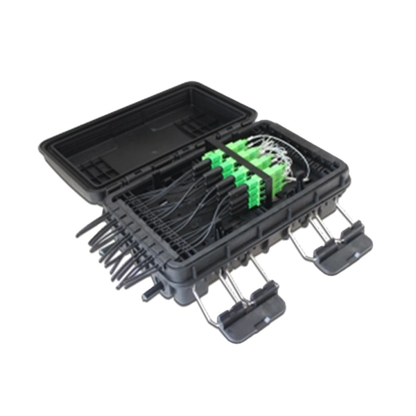
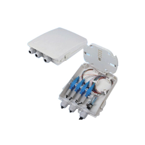
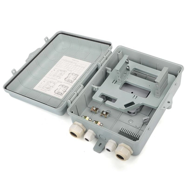
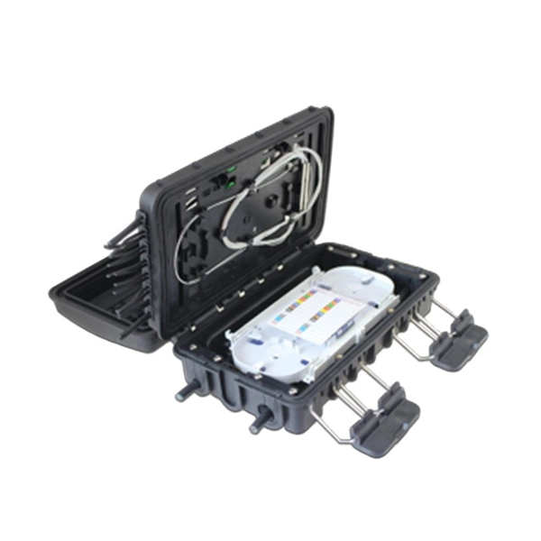
Learn how to splice 4-fiber optic cables using ODF in this complete step-by-step tutorial. Whether you are a beginner or a professional in fiber optic networking, this guide will help you splice fiber cables accurately, manage connections with ODF panels, and ensure. This complete guide explores everything you need to know about ODFs — from their structure, types, and key components, to installation best practices and modern design trends. Whether you're building a central office, data center, or FTTx distribution network, understanding the right ODF. How to Splice 4-Fiber Optic Cable with ODF | Step-by-Step Fiber Optic Splicing Tutorial. This guide demystifies ODF, exploring their design, core functions, types, and how they. An Optical Distribution Frame (ODF) is the central hub for fiber splicing, termination, patching, and cable protection in modern optical networks. It's where incoming and outgoing cables meet. It does four key things: Think of it as the central hub for your fiber network. Without it, cables get tangled. This article explores the types, components, applications, installation, and maintenance best practices, providing a.
[PDF]
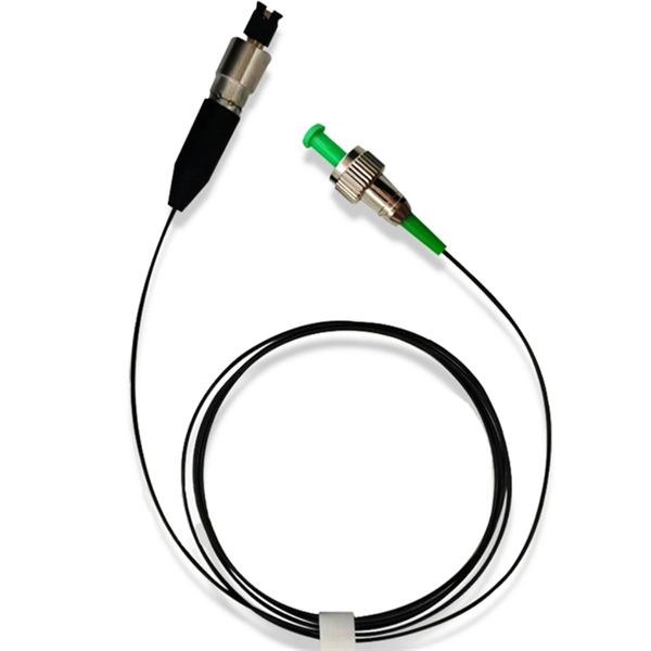
As light in fibers often does not have a well defined polarization state, it is important that a fiber-optic attenuator exhibits only a minimum amount of polarization dependence. Generally, the obtained insertion loss has some dependence on the optical wavelength. Some attenuators have a relatively strong wavelength dependence and are made for working in narrow wavelength regions, e.g. with a bandwidth of only 20 nm around a center wavelength of 1550 nm. Others are optimized for a weaker wavelength dependence, making them u. For single-mode devices, the insertion loss can not depend on the direction of propagation, as long as no non-reciprocal parts are used, as e.g. in a Faraday isolator. For multimode devices, however, some loss difference is possible in conjunction with a mode dependence. For many applications, it will not be a problem if the obtained insertion loss slightly deviates from the specification (e.g. by 1 dB), or if it slightly changes over time. Example cases, however, one may require a higher precision. Most fiber-optic attenuators exhibit a relatively high return loss (at least several dozens of decibels), i.e., there is not much light which is reflected back into the input fiber. For some sensitive applications, e.g. when using an attenuator before or after a high-gain fiber amplifier, one may have two use attenuators with particularly high retu.
[PDF]
The beamsplitter is constructed in a cube shape, with dimensions of 25. 4 mm, providing a robust and stable platform for optical systems. This product is a non-polarizing cube beamsplitter, model 14NBC-25. 4-50/50-700-950, manufactured by Standa. It is designed for use in the 700-950nm wavelength range, making it suitable for a wide range of optical applications. The beamsplitter has a 50:50 reflection to transmission ratio, meaning. 【Professional Teleprompter Glass】NEEWER high definition cube beam splitter is constructed with ultimate craftsmanship for a crystal clear reflection. It is perfect for teleprompters to be used in video productions, education, e learning, live events, traditional newsrooms, television studios, etc. An Optical Beamsplitter is an optic or optical device that is used to split a beam of light in two. Newport offers a wide variety of Beamsplitters in various shapes. It is a crucial part of many optical experimental and measurement systems, such as interferometers, also finding widespread application in fibre optic telecommunications. The split ratio of light transmittance and reflectance is 1:1 and is called a half mirror. Good fit for large beam size applications at a reasonable price. Our plate beamsplitters have a coated front surface that determines the beam splitting ratio while the back surface is wedged and AR coated in order to minimize ghosting and interference effects. Pellicle beamsplitters provide excellent.
[PDF]
It's important to watch the supply reel while installing to ensure the minimum bend radius isn't compromised. Use proper cable pulling lubricants. Sequentially mark the pulling role for easy identification. Use extreme caution when removing the pull eye. Fiber optic cable is surprisingly strong, durable and pliable; however, several best practices should be followed to ensure a successful cable installation. This article explores recommendations for pulling and installing fiber optic cable. Most fiber optic cables boast a pull strength of 100 – 200. That's where investing in high-quality patch cords makes a real difference—they arrive with better polishing, protection caps, and lower insertion loss, reducing the margin for error during deployment. When discussing installation mistakes, endface contamination deserves special attention because. Fiber optic troubleshooting is an essential skill for network administrators, technicians, and engineers responsible for maintaining and repairing fiber optic systems. These high-speed, high-capacity communication networks are increasingly replacing copper cables, offering superior performance and. Harnessing the full potential of fiber optics hinges greatly on the quality of its installation. During installation, all curvatures should be smooth. The cable should be bent as little as possible. Most fiber damage does not come from normal operation after the system is live.
[PDF]

High Initial Investment Costs:The transition to LED and smart lighting systems involves substantial upfront costs, estimated at around $1. 5 billion for large-scale implementations in South Korea. The South Korea Lighting Distribution Cabinet Market was valued at 8. 04 billion in 2025 and is projected to grow at a CAGR of 6. 17% from 2026 to 2033, reaching an estimated 12. This expansion is fueled by rising demand across industrial, commercial, and technology-driven. The South Korea LED and Smart City Lighting Market, valued at USD 1. 7 billion, is growing due to demand for IoT-enabled systems, energy savings, and urban development in cities like Seoul and Busan. 7 billion, based on a. Market Forecast By Offering (Hardware, Software, Services), By Installation Type (New Installations, Retrofit Installations), By End Use Application (Indoor, Outdoor), By Communication Technology (Wired, Wireless) And Competitive Landscape The South Korea smart lighting market is experiencing. Find local businesses, view maps and get driving directions in Google Maps. Market segmentation highlights a preference for hanging cabinets, likely due to space efficiency. 15 million by 2026–31, driven by smart city pilots and commercial modernization. The evolution of South Korea's smart lighting market is rooted in the country's early nationwide commitment to digital infrastructure.
[PDF]
An optical network is a communication system that leverages light to convey information across distances, encoding data into rapid flashes of light instead of relying on electrical voltage changes. At the heart of this ecosystem lies the Optical Transport Network (OTN) — a framework defined by the ITU-T (notably G. 709) that has become the foundation for modern optical communications. This method allows engineers to manage the exponential growth in global data traffic generated by. A passive optical network (PON) is a system commonly used by telecommunications network providers that brings fiber optic cabling and signals all or most of the way to the end user. Depending on where the PON terminates, the system can be described as fiber to the curb, fiber to the building or. An Optical Transport Network (OTN) is a transmission network based on wavelength division multiplexing (WDM) technology. It is a specific type of transmission network that transmits data and manages it using optical signals. OTN is built on a series of protocols, including G. It is designed to provide a high-speed, scalable, and reliable infrastructure for the transmission of data between different network nodes. While there are many subtle differences, a clear distinction between active optical networking and PON topology is PON's use of a.
[PDF]
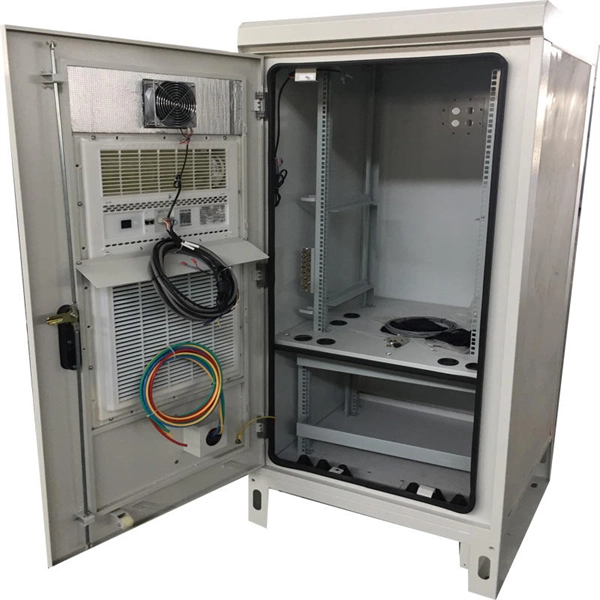
This guide provides a detailed, professional procedure for installing a Residual Current Circuit Breaker (RCCB)—a device essential for protecting people from the severe danger of electric shock. The steps outlined here are fundamental to ensuring the RCCB functions. It is an electrical protective device that protects electrical circuits and devices from some electrical faults such as leakage faults, electrical shock, current unbalance due to equipment failure, etc. It works on the principle of sensing residual current which is why it is called a residual. Distribution board is a safe system designed for house or building that included protective devices, isolator switches, circuit breaker and fuses to connect safely the cables and wires to the sub circuits and final sub circuits including their associated Live (Phase) Neutral and Earth conductors. Residual-current devices, commonly referred to as RCDs, are used in many practical applications. They can be found in fuse boxes, electrical switchgears or industrial machine control systems. Therefore. To wire an RCD fuse box correctly, start by reviewing the diagram to identify each circuit and its corresponding components. Understanding the layout helps prevent mistakes and ensures safe wiring. floor in a multi storey building. The Sub distribution board is connected and supplied from the Main Distribution Board through different wires and cables rated.
[PDF]
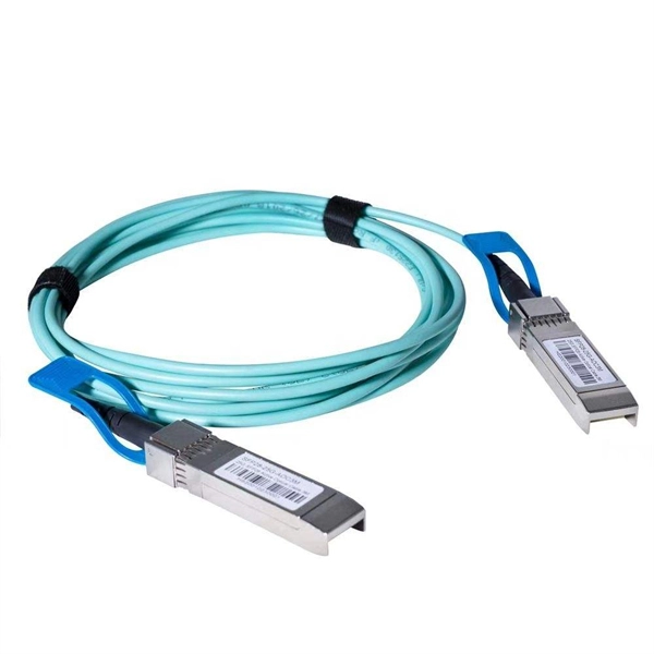
They directly point to the module type. Additionally, observing the color of the optical module's pull tab is a straightforward way to check it. Multimode: Pull tabs are typically black. Another very direct method is checking the. How to distinguish whether an optical fiber module is single-mode or multi-mode? Optical modules are core photoelectric conversion components in fiber-optic communication, data centers, enterprise networks, and telecom transmission systems. Correctly distinguishing single-mode and multi-mode. Understanding whether your SFP module is single-mode or multimode is crucial in network design. The choice impacts the transmission distance, data rate, and cost of your setup. Typically, single mode SFP modules are labeled as "SM" or "single mode," while multimode modules may be labeled as "MM" or "multimode. ". To determine whether the SFP module in your hand is single-mode or multi-mode, the most straightforward method is to check the color of the pull ring, for example, blue pull rings and red pull rings are single mode, and black pull rings are multimode. Multimode (MMF) SFP modules involves a cross-referencing protocol of physical bail colors, EEPROM telemetry, and wavelength specifications. Precise verification prevents "Ghost Links" and Mode Field Diameter (MFD) mismatches that degrade 800G AI fabric performance.
[PDF]
Picking up the best router for fiber internet isn't just about going to the market and choosing one of the best wireless routers. Instead, you need to carefully look at its specs, performance, and the type of securit.
[PDF]
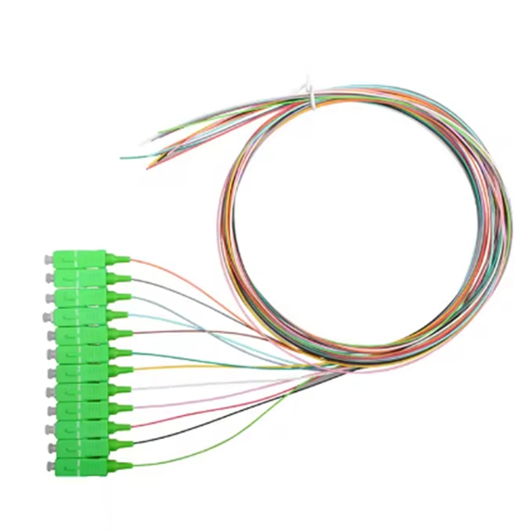
In this informative guide, we'll walk you through the step-by-step process of stripping and preparing fibre optic cable for termination, covering techniques, tools, and best practices to help you achieve successful terminations in your fibre optic installations. Strip the jacket and buffer: Using a fiber optic cable stripper, remove the outer jacket and buffer tubes from the cable. Make sure to strip the appropriate length, as specified by the manufacturer. Be cautious not to damage the fibers during this process. Cleave and cut the fibers: After. In this instructional video, Bob Licari, Test Equipment Product Manager, demonstrates a simple way to strip optical fiber. more Audio tracks for some languages were automatically generated. Eventually, this imperfection can initiate a crack when the. It is impossible to work in fiber optics without having a good working knowledge about cables and skills in pulling, placing and preparing cables for termination and splicing. Properly stripping the cable and preparing the fibre ends ensures a clean and secure connection, leading to optimal signal transmission and network performance. Terminating fiber optic cables essentially means putting connectors on fiber optic cable so that you can connect the cable to various devices or network components. Think of it as the equivalent of connecting the dots in a complex puzzle; without proper termination, the whole system can break down.
[PDF]
This guide covers the critical steps, from selecting the right electrical cable tray and performing accurate cable fill calculations to managing a safe cable pull through and ensuring all bonding and grounding requirements are met. But before you lay the first tray or clamp down a single cable, you need a solid plan. This guide breaks down the process step by step. Plan the Route Before You Drill No installation should start without a plan. For licensed electricians, mastering these principles is essential. Cable tray installation implies the construction of an electric road that will be safe. In order to get it right, installers are supposed to adhere to a plan that ensures that wires are kept cool and the building is stable. The beginning of success is to review the Bill of Quantities (BOQ) so that. Cable tray systems provide a safe, organized, and flexible method for supporting insulated conductors and cables in commercial and industrial electrical installations. When properly selected and installed, cable trays simplify routing, improve accessibility, and support future expansion while. Proper installation of cables in trays is critical for maintaining an efficient and safe electrical system. This process is integral to determining the optimal arrangement and configuration of cable trays, which are essential for routing and supporting electrical cables within buildings and.
[PDF]
