
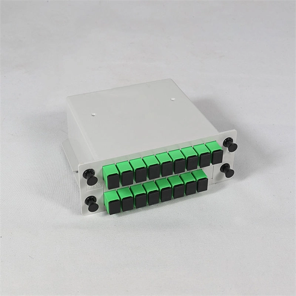
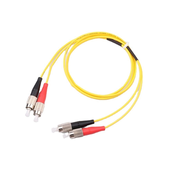
This guide, provided by Fibconet, delves into the structure and working principle of fiber optic connectors and outlines the critical steps for creating a successful connection. Understanding Fiber Optic Connector Structure. How To Install Fiber Optic Cable Connectors? There are many types of fiber optic connectors, including SC, LC, FC, ST, D4, MU, MT/MPO, etc. These connectors can be divided into single-mode and multi-mode fiber optic connectors according to their structure and purpose. To learn more about the types. This tab provides a brief explanation of how we determine several key specifications for our 1x2 couplers. 1x2 couplers are manufactured using the same process as our 2x2 fiber optic couplers, except the second input port is internally terminated using a proprietary method that minimizes back. Fiber optic adapters, also known as couplers, play a crucial role in fiber optic networks by providing a connection point between two fiber optic connectors. In this tutorial. Fiber Optic Transceivers: For converting signals between optical and electrical form. Cleaver: For precisely cutting the fibers. Safety Equipment: Gloves. Starting with site surveys and permissions, to installing fiber optic cable and emphasizing the process as a key stage in mastering fiber optic installation, to the careful handling of cables and high-stakes splicing, each stage is critical.
[PDF]
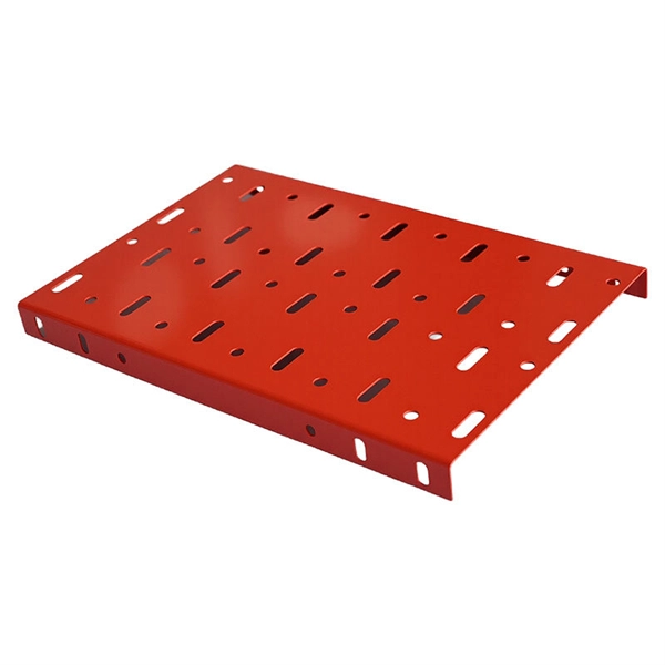
The price of FRP trays can range from $10 to $50 per meter, depending on the specifications such as size, design, and environmental factors. Cable trays are vital in electrical installations, providing secure pathways for power, communication, and control cables across residential, commercial, and. Using 3/4" conduit for each cable at. 34/ft using 20 ft sections in tray and 10 ft sections for the drop. 21/ea for every 6 ft of cable for the drops and conduit couplers at. Understanding the key factors that influence their pricing helps engineers, contractors, and. This guide covers the critical steps, from selecting the right electrical cable tray and performing accurate cable fill calculations to managing a safe cable pull through and ensuring all bonding and grounding requirements are met. For licensed electricians, mastering these principles is essential. Market context (at-a-glance): Industry analysts valued the global low voltage wire & cable market at roughly USD ~ 145. 7 billion in 2024 and is projected to grow at a CAGR of 7. 2% from 2025 through 2034. Nearly 70% of new homes are now built with low voltage systems (industry estimate) meaning that. Ladder type cable trays are built for heavy-duty routing. In power-heavy areas, they prevent failures that would be far more expensive than the tray itself. Perforated cable trays sit in the middle. They cost less than ladder.
[PDF]

In this guide, learn the basics of reading and interpreting electrical wiring diagrams. Follow Along on SkillCat: "Wiring Diagrams" Course! Want to test your knowledge? Skip to the quiz!. In this article, you'll learn how to read, understand and use a wiring diagram. An electrical wiring diagram could be a single page schematic of how a ceiling fan should be connected to the power source and its remote switches. A wiring diagram may include the wirings of a vehicle. For example, how. Electrical wiring diagrams are an essential tool for electricians, engineers, and automation technicians. Proper interpretation is crucial for understanding the operation of devices, diagnosing faults, and working safely with electrical installations. Understanding how to read electrical diagrams. In order to trace control system problems to the core, the ability to read and interpret various resources, from facility-level diagrams to machine-level wiring layouts, is critical. The engineering world is crammed full of drawings and diagrams of every possible kind. It shields sensitive equipment from dust, moisture, and. After reading and studying this handbook, electricians (or would-be electricians) will have a firm grasp on the many symbols used in electrical diagrams.
[PDF]
This video shows real on-site footage of electrical installation, demonstrating safe and standardized wiring methods used by professionals. You will learn to build a safe, efficient, and professional electrical system today. Circuit breaker wiring configurations involve organizing main switches, busbars, and branch breakers within a distribution box. Proper setups. An electrical panel box, also known as a breaker box or a distribution board, is a crucial component of any electrical system. It serves as a central hub for distributing electricity throughout a building, ensuring that power is delivered safely and efficiently to all the required locations. Choose the right box based on environment (indoor/outdoor), load capacity, and durability. Check for proper IP/NEMA ratings and material quality. And all the switching and protective devices are installed in the. Connection method: Each switch takes a wire from the incoming point and connects it to the incoming end of the switch, or uses parallel connection to reduce the difficulty of wiring. Wiring Direction: Wiring between the main circuit breaker and each branch circuit breaker in the box generally.
[PDF]
When it comes to testing fiber optic cables, a Visual Fault Locator (VFL) is an essential tool in your toolkit. A VFL is used to detect faults, breaks, or bends in fiber optic cables by emitting a bright red light that is visible even through the fiber's jacket. Let's dive into everything you need to know about mastering VFLs. In the. Finding a break in a fiber optic cable can be challenging but is essential for maintaining a stable network. Common Indicators of a Cable Break Signal. Here Kingfisher's experienced engineers share their experience in best practices and procedures for fiber optic testing related mostly to installation and maintenance. We hope that by sharing our knowledge, we will help grow our industry. Please enjoy & pass on these notes. The following are key methods and techniques used for optical fiber cable line failure positioning: Visual Inspection: Perform a visual inspection of the. Locating faults in fiber optic cables requires specialized tools and techniques. Look for dirt, scratches, or damage on the connectors. Clean. To ensure the quality and continuity of fiber optic services, it is essential to identify and locate fiber optic cable faults as quickly and accurately as possible. In this article, you will learn about some of the common methods and tools for fiber optic testing and troubleshooting.
[PDF]
Buy Panduit LabelCore Fiber Optic Cable Identification System Self-Laminating Laser/Ink Jet Labels at SHI. See detailed specifications and benefit from expert support. Shop IT hardware and software products with SHI now!. Indoor & outdoor fiber cable high visibility markers, id labels, printers, warning signs & posts, cable id sleeves and more for fiber optic applications. Check each product page for other buying options. Need help? Explore write-on fiber optic cable tags with self-laminating protection. Keep your cables organized and clearly labeled with writable identification solutions. The Multilink cable markers utilize a simple and quick installation that allows the installer to simply wrap the marker around the selected cable without the need for special tools or adhesives. The UV stabilized body will not degrade in outside applications and a variety of colors allows easy. According to research conducted by industry experts that shows network failures cost businesses the equivalent of five thousand dollars per minute. If technicians aren't able to quickly recognize the correct cable, these minutes can add up quickly. The TIA/EIA-606-A standard has created a unified system that specifies a "common" method of labeling the complete telecommunication infrastructure. PANDUIT Labeling Software packages include all label formats for quick and.
[PDF]

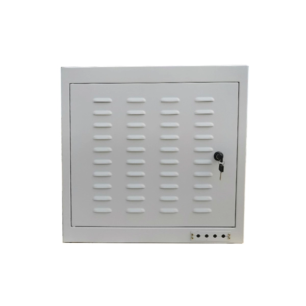
In this article, we will explore the specifications for household distribution boxes and provide guidance on how to install them correctly. Whether you're an electrician or a DIY enthusiast, this guide will help you understand the basics of home electrical distribution. more Welcome to our. A distribution box is the heart of any electrical system. It takes the incoming power and safely distributes it to different circuits throughout your building. While many families are familiar with these boxes, there is often a lack of understanding regarding their specifications and proper. Strictly speaking, the word “Distribution Box (D-box)” can refer to two categories: electrical distribution boxes and septic tank distribution boxes. This article mainly talks about the first one. An electrical distribution box, also known as a power distribution box, panelboard, or consumer unit. Electrical wiring powers everything in your home, from lights and outlets to major appliances. Whether you're building new or updating an older system, the way your wiring is planned and installed affects how safely and efficiently everything runs. We'll break down the key parts of a home. This article is going to be very helpful for you, if you want to learn about how appliances, Motors, Generators, Light bulbs, circuit breakers, float switch, and Contactors are wired up.
[PDF]

The cost to install fiber optic cable ranges from $1. 50 to $42 per foot, with installation costs accounting for 60-80% of total project expenses. According to the Fiber Broadband Association's 2025 report, median costs are $8 per foot for aerial builds and $18 per foot for. Understanding the costs of fiber optic cable is a top concern for businesses planning network infrastructure upgrades. Whether you're expanding your data center, connecting multiple buildings, or future-proofing your connectivity, accurate pricing information helps you budget effectively. With 19+. Whether you're running fiber to a home or a data center, here's exactly what contractors are charging in 2026. fiber projects, we've assembled current material rates, labor burdens, and hidden fees. This guide presents typical price ranges in USD to. Fiber optic cable installation costs between $1,500 and $7,000 for your home, with prices varying by cable length and installation method. The installation type you choose and the layout of your property determine the total labor and materials needed for your project. Cost data covers project ranges and per unit estimates to help buyers budget for fiber installations, whether.
[PDF]

When it comes to testing fiber optic cables, a Visual Fault Locator (VFL) is an essential tool in your toolkit. A VFL is used to detect faults, breaks, or bends in fiber optic cables by emitting a bright red light that is visible even through the fiber's jacket. It's a cost-effective and. A Visual Fault Locator which can be also called visual fault identifier (VFI), fiber fault locator, fiber fault detector, etc., is a visible red laser light designed to inject visible red light energy into an optical fiber. Using a VFL to diagnose issues can save time and cost when diagnosing an. A visual fault locator is a compact, handheld device that emits a visible light beam, typically in the red wavelength range, through a fiber optic cable. It works by injecting a visible red laser light into the fiber, which can be seen through the jacket or at the end of the cable. If the light doesn't come out the other side, there might be a problem. You. And in the end we will show you how to use an old cell phone's camera to detect light in a fiber optic system. It uses a bright incandescent bulb or visible LED source to.
[PDF]

This article delves into the intricate steps of busbar selection, preparation, and installation, ensuring efficient and safe power distribution. You'll discover the essential tools and techniques. FlexLine® busbars PSX go hand in hand with the flex terminals of the FlexLine® protection devices by following an one-size-fits-all approach. Whenever the neutral conductor terminals are not required, the flex terminals accommodate this busbar pin without any mechanical or electrical connection. BEIENE Smart 3 in 1 Busbar Processing machine is with our Intelligent 3D Busbar Program software Smartnest. From 3D Drawings, your busbar can be processed directly. Also can be optimized the production by the nesting function !. more BEIENE Smart 3 in 1 Busbar Processing machine is with our. 40 mm bar centre distance, 3-pole, space-saving plug-and-lock connection from the front, support suitable for top-mounting, all-round contact hazard protection. Our Mother company was founded in 1955 which is the Top Hydraulic research and developing institute in China! “Say Goodbye to CNC Machine, Open your Intelligent Times” this is our commitment to each customer !.
[PDF]

Connect the phase and neutral wires from the input power supply to the input of the Main MCB. They can correct voltage, but they have no effect on power factor. They are installed in series between the Source and Load. They are a voltage source, they add or subtract. When you're towing something much heavier or lighter than usual, you'll need to make adjustments to your weight-distribution hitch. Fortunately, adjusting a weight-distribution hitch for safe towing is fairly straightforward. But if you need more guidance on how to connect your hitch in the first. This green leaf icon designates information specifically for Vista® Green Underground Distribution Switchgear that uses a CO mix insulating gas. Unless otherwise designated, instructions provided apply to all manual 2 Vista switchgear products. Take the appropriate rating of MCB and RCCB as per your load requirements. Identify the Input and Output sides of the MCBs and RCCBs. If you use. Use the Exchange admin center (EAC) or Exchange Online PowerShell to create, modify, or remove distribution lists in your Exchange Online organization. Exchange Online supports four types of groups that can be used to distribute messages: Distributions lists that can be used only to distribute. This bulletin contains instructions for installing Square D brand I-Line circuit breaker power distribution panelboards.
[PDF]

This guide covers the critical steps, from selecting the right electrical cable tray and performing accurate cable fill calculations to managing a safe cable pull through and ensuring all bonding and grounding requirements are met. Cable tray installation implies the construction of an electric road that will be safe. In order to get it right, installers are supposed to adhere to a plan that ensures that wires are kept cool and the building is stable. The beginning of success is to review the Bill of Quantities (BOQ) so that. Whether you're building a commercial setup or upgrading an industrial plant, proper cable tray installation ensures neat wiring, safe access, and easy maintenance. But before you lay the first tray or clamp down a single cable, you need a solid plan. This guide breaks down the process step by step. Whether you're an experienced electrician or a DIY enthusiast, this video is perfect for you. more. Installing a cable tray system requires careful planning to ensure it can support the weight of the cables and adheres to electrical safety codes. Here is a step-by-step guide on how to install a standard metal cable tray system (e., ladder or perforated type). Before starting, ensure you have. Proper installation of cables in trays is critical for maintaining an efficient and safe electrical system. This is why proper planning and execution are.
[PDF]

This document provides guidance on installing, pairing, configuring, and using the Wiser Power Micromodule with the Wiser Home app. It explains how to set up device types, rename and assign locations, adjust nominal power, and monitor energy consumption. NOTICE is used to address practices not related to physical injury. Was this article helpful? Sorry, our feedback system is currently down. Please try again later. Turn off power at the service panel and remove the existing wall switch. Unfold all of the wires from within the junction box. Turn on power and use a voltage detector to identify the live wire; this is your line wire. Turn off power and. Lock out and tag the input circuit before accessing the wiring connections. Make sure that the terminal connection area does not come in contact with the metallic parts of any device installed in the same location. Do not. The I/O module is intended for residential, commercial, and light-industrial environments. The I/O module is an independently mounted electronic control system with fixed wiring. The I/O module is suitable for mounting in fuse boxes conforming with standard DIN43880 and DIN19, and having a slot. The processor core of Keyestudio PRO MICRO development board is ATMEGA32U4-MU, fully compatible with ARDUINO. It contains everything needed to support the microcontroller; simply connect it to a computer with a USB cable to get started. It has 18 digital input/output pins (of which 5 can be used as.
[PDF]