
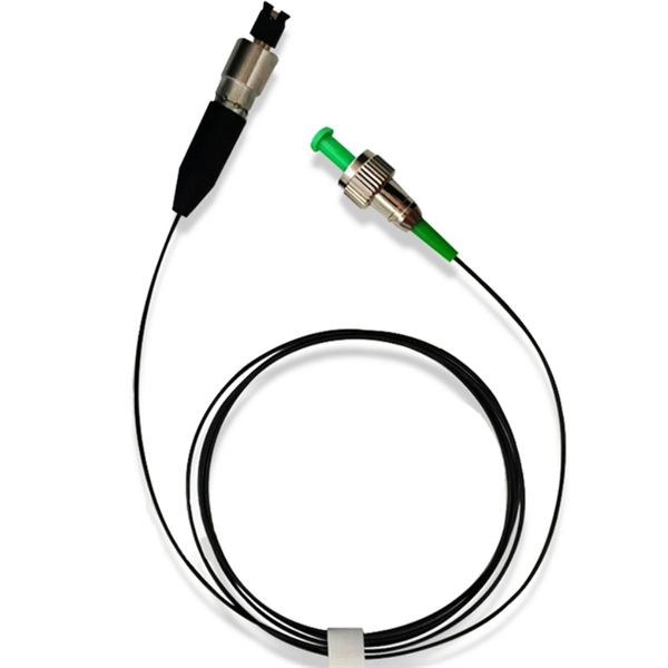
Mainly 9steps: Step 1: cut cable with cutting machines in lengths Step 2: put the connector spare parts on the cable Step 3: Strip cable jacket, coating till bare fiber, and make all parts in ready Step 4: Insert fiber into ferrule, glue dispenser and heat oven Step 5:. Mainly 9steps: Step 1: cut cable with cutting machines in lengths Step 2: put the connector spare parts on the cable Step 3: Strip cable jacket, coating till bare fiber, and make all parts in ready Step 4: Insert fiber into ferrule, glue dispenser and heat oven Step 5:. Learn how to make a fiber optic patch cord step by step, from preparation to testing, for reliable high-performance connections. Most guides on making fiber optic patch cord 1 s feel incomplete. They often focus on the final assembly steps, leaving the foundational stages a mystery. From cable cutting to connector assembly and testing, you will gain valuable insights into the production of. Fiber optic patch cords and Pigtails are very important passive fiber optic components in fiber optic networks. Use the fiber optic cleaver to cut the. This document describes the installation and use of the mode-conditioning patch cords listed in Table 1. A mode-conditioning patch cord is shown in Figure 1 IEEE 802. 3z-compliant optical fiber assembly consisting of a single-mode fiber permanently coupled off-center to a 62. 5-micron multimode.
[PDF]

In this video, I'll show you how to build a simple and effective short circuit protection circuit using a relay. This DIY project is perfect for anyone looking to protect their electronics from accidental shorts. Last Updated on February 15, 2026 by Swagatam 117 Comments In this post I will try to explain the making of a simple 220 V, 120 V AC mains short circuit breaker using an SCR and a triac combination, (researched and designed by me). The circuit is an electronic version of the normal main circuit. One possible solution to the problem of overcurrent is to use a variable bench power supply with a current limit function. These power supplies allow You to set a current limit, preventing a high current flow when a mistake occurs. This circuit will. Why Publish? How to Make Short Circuit Protection Circuit: Hii friend, Today I am going to make a circuit for Short Circuit protection. This circuit we will make using 12V Relay. How this circuit will Work - when short circuit will occur on the load side then the circuit will be automatically cut o. In this tutorial, we will see how to make a short circuit protection using Relay. Many times accidentally terminals of batteries and other power supplies get short-circuited. Due to this, they get hot and start degrading. In the case of lithium-ion or lithium-polymer batteries, they may catch fire.
[PDF]
This article provides a step-by-step guide on terminating fiber optic cables, covering essential tools, methods, and best practices. High-speed fiber optic networks form the backbone of modern communications systems. more Audio tracks for some languages were automatically generated. This is where the of the end of fiber and the ferrule that holds it in the connector are polished to give a uniformly flat and clear surface for the best optical performance and minimal signal loss. Optimal performance can be achieved by following the correct process for termination of the fiber circuit—a task which requires the use of a wide range of. Terminating fiber optic cables is a critical skill for telecommunications technicians. Proper termination ensures reliable network performance and minimal signal loss across fiber infrastructure.
[PDF]
On average, commercial projects range from $5,000 to $20,000 per mile underground and $40,000 to $60,000 per mile for aerial deployment. Individual business connections often cost between $15,000 and $30,000 for 100–200 network drops. Buying fiber optic installation services involves several cost components, with total price influenced by length, location, and access. The main cost drivers include trenching or aerial deployment, materials, labor hours, and any required permits. This guide presents typical price ranges in USD to. The initial cost of installing fiber optic cables can vary depending on the chosen installation method and specific project requirements. In preparing this second edition of the Fiber Deployment Cost report, Cartesian gathered inputs from a wide variety of firms building. Getting accurate cost estimates is crucial for winning fiber installation bids. Smart contractors know that underground vs aerial installation pricing varies wildly based on location and project conditions. This breakdown gives you real numbers to build better estimates. We'll show actual costs for. Home and business buyers typically see a wide range of costs for fiber optic projects, driven by distance, fiber type, conduit needs, and labor. The price can shift based on underground vs. aerial routes, equipment choices, and whether new permits are required. Some variables are less determinate.
[PDF]

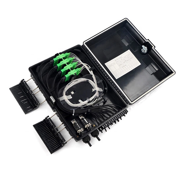
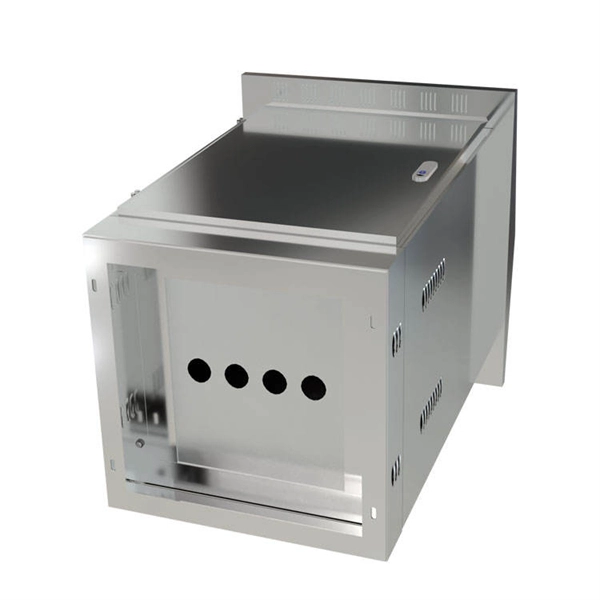
First, connect each pre-terminated fiber optic cable to the adapter panel separately, making sure the ports correspond one-to-one; then fix the fiber optic adapter panel to the front panel of the distribution box with the bend radius control clip. In general, installing the optical fiber distribution box can be divided into three steps: installing the optical fiber distribution box on the rack, introducing the optical cable into the optical fiber distribution box, and planning the optical fiber path in the optical fiber distribution box. The. Bottom installation: Select a proper installation position in the equipment room and drill four holes in the floor according to the dimensions shown in the manual. Fix the rack to the ground with expansion bolts. Top installation: Dimensions of four connection holes on the top according to the. The Optical Distribution Box (ODB) is high-density 2-in-2-out fiber box solution. Designing with a compact size of 340x220x100mm, the cabinet accommodates 1x2,1x4,1x8 and 1x16 etc. The 4 ports are sized for main cable from 9 to 16mm in diameter, along with 16 3mm cables. Accessory Kits:. Install the optical fiber distribution box on the rack. Ensure that the box is installed firmly and horizontally, and the deviation of perpendicularity is not greater than 3mm.
[PDF]

An ideal optical splitter will distribute the light power according to mathematical principle. This is because each of the 8 output ports of the splitter will receive only one-eighth of the. Thorlabs' Single Mode 1x8 Fiber Optic Planar Lightwave Circuit (PLC) Splitters allow a user to split a single input signal evenly into eight output signals, which is ideal for passive optical networks (PON) and other high-channel-count applications. 1×8 splitter means it takes one input fiber and splits the signal into eight outputs. It doesn't need power — it's passive! Great for sharing one signal with many devices, like in FTTH (Fiber To The Home) networks. But light doesn't just split for free. Sharing means each output gets less than the. If we operate with absolute gains measured in relation to 1 milliwatt (mW), they are expressed in dBm, and are calculated as follows: Power Level (dBm) = 10 lg ( mW / 1 ) For “household” needs, in order not to calculate mW to dBm and vice versa every time, here's a ready-made correspondence table:. For instance, a 1:8 splitter ratio signifies an equal distribution of incoming optical power among eight output ports, with each port receiving 1/8th of the total power. It has one input port and eight output ports, making it ideal for applications where a signal needs to be.
[PDF]

Connect the phase and neutral wires from the input power supply to the input of the Main MCB. Learn how to install a distribution box safely and correctly. Covers wiring, placement, standards, and expert tips for a compliant setup. It takes the incoming power and safely distributes it to different circuits throughout your building. Learn how to wire a distribution box step by step! This video shows real on-site footage of electrical installation, demonstrating safe and standardized wiring methods used by professionals. Below is a quick checklist of everything you will need for a safe and efficient installation: Connecting a distribution box involves several steps to ensure proper electrical flow. It is usually equipped with circuit breakers, fuses, terminal connectors, and other components. It is mainly used to isolate fault circuits, prevent overload, and ensure the safe operation of. Box installation: Make sure that Distribution box has been correctly installed and fixed. Location determination:. An electrical panel box, also known as a breaker box or a distribution board, is a crucial component of any electrical system. It serves as a central hub for distributing electricity throughout a building, ensuring that power is delivered safely and efficiently to all the required locations.
[PDF]

The Optical Time Domain Reflectometer (OTDR) is useful for testing the integrity of fiber optic cables. It can verify splice loss, measure length and find faults. The OTDR is also commonly used to create a "picture" of fiber optic cable when it is newly installed. The Contractor tasked to perform testing or splicing on any fiber optic cable will follow these testing standards to fulfill their contractual obligations. The Contractor must utilize the correct equipment and testing techniques to gain acceptance, or the work cannot be approved. Later, comparisons can be made. For every fiber optic cable plant, you will need to test for continuity, end-to-end loss and then troubleshoot the problems. If it's a long outside plant cable with intermediate splices, you will probably want to verify the individual splices with an OTDR also, since that's the only way to make. ic system. Fiber optic testing of a newly installed system not only verifies that the system meets its design requirements, but also creates a performance baseline for all future testing and troubleshooting of t at system. What is Fiber Optic Splicing and Why is it Needed? – #1. Use and Maintain Your. This guide reveals the secrets to fusion splicing with little fluff—just proven, straightforward techniques refined from years of work in the field. The guide provides the complete workflow, covering safety precautions, tool selection, fiber preparation, fusion operation, quality control, and.
[PDF]

This article will give you an overview of the use cases for fiber-optic networking, some of the terms used in fiber networking, and suggestions for setting up a fiber network. Once you understand the basic concepts, you can check out my Recommended Equipment section toward. Fiber tapping is a network tap method that extracts signal from an optical fiber without breaking the connection. Tapping of optical fiber entails diverting some of the signal being transmitted in the core of the fiber into another fiber or a detector. Fiber to the home (FTTH) systems use beam. Optical fiber is a technology used to transmit data by sending short light pulses along a long fiber, which is typically made of glass or plastic. In optical fiber communication, metal wires are preferred for transmission because the signals travel more safely. Optical fibers are also resistant to. Photo: Light pipe: fiber optics means sending light beams down thin strands of plastic or glass by making them bounce repeatedly off the walls. This is a simulated image. Note that in some countries, including the UK, fiber optics is spelled "fibre optics. " If you're looking for information online. This manual covers everything about fiber optic cables, how they work, where they are used, and what is new in this area of technology. The choice of fiber optic cable depends on the specific needs of the application, as well as the.
[PDF]
The detailed steps outlined herein provide a comprehensive understanding of optical attenuator installation and adjustment. Proper execution enhances the efficiency and stability of the attenuators and the overall communication system. Fibre optic attenuators, also called optical attenuators, are passive devices used to reduce the power level of an optical signal. Assemble all necessary tools and equipment, such as a fiber cleaver, fusion splicer, optical power meter, and connector cleaning tools. These are the cornerstones of a seamless installation. Equally. Having a deep understanding of how to select a fiber optic attenuator, regardless of the type—fixed or variable—and the type of fiber and connector is critical to the durability and maintainability of a reliable network. Taking optical power measurements before installation of a fiber optic. Optical Signal Attenuation is the single greatest factor limiting the distance and performance of your network. Understanding it is crucial for anyone involved in data centers, telecommunications, or enterprise networking. In this. 📦 For purchasing, use the RP Photonics Buyer's Guide for optical attenuators. It provides an expert-curated supplier directory, buyer-focused technical background information, and structured selection criteria to support professional procurement decisions. Optical attenuators are devices that.
[PDF]
Multimode fiber optic cable has a larger core, typically 50 or 62. 5 microns that enables multiple light modes to be propagated. Because of this, more data can pass through the multimode fiber core at a given time. The maximum transmission distance for MMF cable is around 550m at the speed of. Multimode Fiber (MMF) has a core diameter, typically 50–100 micrometers, has ability to transfer multiple modes of light through the fiber core, uses lower-cost electronics (LED, VCSEL) operates at the 850 nm and 1300 nm wavelength and is used for short distance interconnections (up to 550m). This Applications Engineering Note (AE Note) discusses the criteria for properly selecting the optimal multimode fiber (MMF) for enterprise applications. Both fiber types play essential roles in today's optical.
[PDF]
As light in fibers often does not have a well defined polarization state, it is important that a fiber-optic attenuator exhibits only a minimum amount of polarization dependence. Generally, the obtained insertion loss has some dependence on the optical wavelength. Some attenuators have a relatively strong wavelength dependence and are made for working in narrow wavelength regions, e.g. with a bandwidth of only 20 nm around a center wavelength of 1550 nm. Others are optimized for a weaker wavelength dependence, making them u. For single-mode devices, the insertion loss can not depend on the direction of propagation, as long as no non-reciprocal parts are used, as e.g. in a Faraday isolator. For multimode devices, however, some loss difference is possible in conjunction with a mode dependence. For many applications, it will not be a problem if the obtained insertion loss slightly deviates from the specification (e.g. by 1 dB), or if it slightly changes over time. Example cases, however, one may require a higher precision. Most fiber-optic attenuators exhibit a relatively high return loss (at least several dozens of decibels), i.e., there is not much light which is reflected back into the input fiber. For some sensitive applications, e.g. when using an attenuator before or after a high-gain fiber amplifier, one may have two use attenuators with particularly high retu.
[PDF]
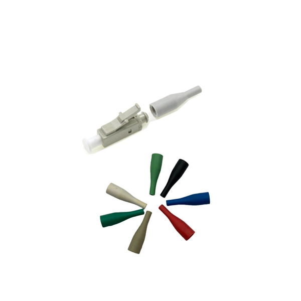
In this video, Joe would display how to connect SC fiber optical connector in 2 minutes. Related product:. Step 4 i s to affix the fiber to the connector. The fiber should be inserted into the connector until it is flush with the ferrule end. Step 5: Let the epoxy cure. These connectors ensure high-quality signal transmission, which is essential for reliable internet and communication services. SC APC connectors offer superior optical. There are many types of fiber optic connectors, including SC, LC, FC, ST, D4, MU, MT/MPO, etc. These connectors can be divided into single-mode and multi-mode fiber optic connectors according to their structure and purpose. To learn more about the types of fiber optic connectors, click here: Types. The global SC fiber optic connector market is valued at approximately 903 million USD in 2025 and is projected to grow steadily, which reflects its continuing role as a standard interface in fiber infrastructure, including plant backbones and industrial automation links, according to SC connector. SC fiber connectors, or Subscriber Connectors, are widely used in telecom and networking for their strong performance and easy handling. They're known for a secure push-pull connection that's quick to insert and remove.
[PDF]

