
In this video, I'll show you how to build a simple and effective short circuit protection circuit using a relay. This DIY project is perfect for anyone looking to protect their electronics from accidental shorts. Last Updated on February 15, 2026 by Swagatam 117 Comments In this post I will try to explain the making of a simple 220 V, 120 V AC mains short circuit breaker using an SCR and a triac combination, (researched and designed by me). The circuit is an electronic version of the normal main circuit. One possible solution to the problem of overcurrent is to use a variable bench power supply with a current limit function. These power supplies allow You to set a current limit, preventing a high current flow when a mistake occurs. This circuit will. Why Publish? How to Make Short Circuit Protection Circuit: Hii friend, Today I am going to make a circuit for Short Circuit protection. This circuit we will make using 12V Relay. How this circuit will Work - when short circuit will occur on the load side then the circuit will be automatically cut o. In this tutorial, we will see how to make a short circuit protection using Relay. Many times accidentally terminals of batteries and other power supplies get short-circuited. Due to this, they get hot and start degrading. In the case of lithium-ion or lithium-polymer batteries, they may catch fire.
[PDF]

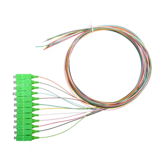
Mainly 9steps: Step 1: cut cable with cutting machines in lengths Step 2: put the connector spare parts on the cable Step 3: Strip cable jacket, coating till bare fiber, and make all parts in ready Step 4: Insert fiber into ferrule, glue dispenser and heat oven Step 5:. Mainly 9steps: Step 1: cut cable with cutting machines in lengths Step 2: put the connector spare parts on the cable Step 3: Strip cable jacket, coating till bare fiber, and make all parts in ready Step 4: Insert fiber into ferrule, glue dispenser and heat oven Step 5:. Learn how to make a fiber optic patch cord step by step, from preparation to testing, for reliable high-performance connections. Most guides on making fiber optic patch cord 1 s feel incomplete. They often focus on the final assembly steps, leaving the foundational stages a mystery. From cable cutting to connector assembly and testing, you will gain valuable insights into the production of. Fiber optic patch cords and Pigtails are very important passive fiber optic components in fiber optic networks. Use the fiber optic cleaver to cut the. This document describes the installation and use of the mode-conditioning patch cords listed in Table 1. A mode-conditioning patch cord is shown in Figure 1 IEEE 802. 3z-compliant optical fiber assembly consisting of a single-mode fiber permanently coupled off-center to a 62. 5-micron multimode.
[PDF]
This article provides a step-by-step guide on terminating fiber optic cables, covering essential tools, methods, and best practices. High-speed fiber optic networks form the backbone of modern communications systems. more Audio tracks for some languages were automatically generated. This is where the of the end of fiber and the ferrule that holds it in the connector are polished to give a uniformly flat and clear surface for the best optical performance and minimal signal loss. Optimal performance can be achieved by following the correct process for termination of the fiber circuit—a task which requires the use of a wide range of. Terminating fiber optic cables is a critical skill for telecommunications technicians. Proper termination ensures reliable network performance and minimal signal loss across fiber infrastructure.
[PDF]
Dubai Electricity and Water Authority (DEWA) extended over 364 kilometres of Fibre Optic (FO) ducts across different areas in Dubai in 2023. This has increased the total length of these cable ducts to 3,998 kilometres, a 10% increase compared to 2022. Fibre refers to a type of internet connectivity where information is transmitted via fibre optic cables. This is in line with DEWA's efforts to build a. As w. media's Global Editor-in-Chief, Grey covers the cloud and data center industry and connectivity ecosystem across APAC and EMEA. In a career spanning over two decades, Grey has dabbled in television, print and online journalism, covering a variety of beats including human rights, health. Please try refreshing the page. Visualize the growth of global connectivity. Flexible No Contract Option At AED 2250 / Month Best fiber internet deals in Dubai: du's cable plans deliver 250Mbps to 1Gbps. Includes free smart router and 24/7 premium support. We do have Etisalat approved and DU approved brands in Fiber optic brand with us. We keep complete Stock Fiber Optic Products from 2 Core FTTH cables to 48Core cables in Single mode and Multimode ( OM2, OM3 and OM4).
[PDF]
The answer is yes, and it's a practice widely used in the industry to distribute signals to multiple destinations without degrading the signal quality significantly. This article delves into the methods, benefits, challenges, and practical applications of splitting fiber lines. In principle, an optical cable can be split, but it's not as simple as just cutting the cable and attaching multiple devices. There are two primary methods of splitting an optical cable: Passive splitting involves using a specialized device called an optical splitter. This device takes the incoming. A fiber optic splitter is a passive optical component that divides a single incoming optical signal into two or more outgoing signals, or combines multiple incoming signals into one. What is Fiber Line. An optical splitter, also known as a beam splitter, fiber splitter, or fiber optic splitter, serves as a vital passive component in optical communication systems. Its primary function is to split the optical signal of one input optical fiber into multiple optical signals and transmit them to. An MPO breakout cable is a fiber optic cable designed to split a single multi-fiber connection into multiple separate connections. Fiber optic splitters have applications such as Fiber to the Home (FTTH) and Passive.
[PDF]
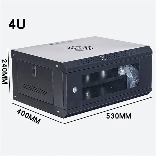
The good news is that network cabinet prices range from as low as $100 for basic wall-mounted units to over $3,000 for specialized outdoor models. However, understanding what drives these costs will help you make a smart buying decision. In this complete guide, we'll break down everything you need. Check each product page for other buying options. VEVOR 6U Wall Mount Network Server Cabinet, 15. 5" Deep, Server Rack Cabinet Enclosure, 200 lbs Max. 5". Explore our top-tier selection of Networking Cabinets and Racks designed to keep your IT infrastructure organized and secure. Whether you're setting up a home lab, a corporate data center, or managing network equipment for a small business, our collection offers robust and versatile solutions. Cabinets are used for storing routers, patch panels, switches and a wide variety of networking equipment and accessories. Network cabinets support large, modular network switches by providing additional space for cable management and. Network cabinets are enclosed systems designed to securely store, organize, and protect networking and IT equipment such as switches, routers, patch panels, servers, power strips, and cable management components. They allow users to secure their data and communication connections. The product will be reserved for you when.
[PDF]

When switching to fiber internet, many users wonder if they're able to use their own router instead of the one provided by their internet service provider (ISP). In this guide, we'll explain router compatibility, setup steps and whether upgrading your router is necessary to maximize fiber speeds. Selecting a single router can be challenging, as there are most likely many that fit the requirements you want. We've done the research for you and put together this in-depth guide that lists multiple options, their details, reviews, and pros and cons. This should help you make an informed decision. Unlike cable internet, fiber connections do not require a cable modem. Instead, you simply plug a wireless router into the ONT provided by your ISP, set it up, and start using the internet. But if you're unsure which router to get, you're in the right place. Instead of using your old router, a high-performance Wi-Fi router designed for fiber optic internet will ensure you seamless streaming, online gaming, and remote work all. This article provides a comprehensive review and buying guide designed to assist in identifying the best routers for fiber internet. We will explore key performance metrics, essential features such as Wi-Fi standards and port configurations, and examine a range of router models optimized for fiber. Yes, you can often use your existing router with fiber optic internet, but there are crucial considerations. This guide will break down everything you.
[PDF]

When selecting a 48 core fiber optic cable, prioritize single-mode over multimode for long-distance, high-bandwidth applications such as telecom backbones or data center interconnects. Look for cables with loose tube construction, robust armor (if outdoor use), low attenuation (<0. 4 dB/km at 1310. • Fiber optic cables are often custom cut to match required lengths for each cable run, or you can order a reel matching your total length and cut segments yourself. It's advisable to include a safety buffer when ordering, with an additional 10% being common practice, despite careful measurement of. Fast data transmission, thinner, lighter cables and long signal range are just a few of the benefits that make fiber optic cable a solid choice for corporate data networking and telecommunications. Fiber cores are the heart of fiber optic cables, transmitting light signals that carry data. Made from either high-quality. But when it comes to selecting the right fiber optic cable for your environment, there are several key considerations and a variety of attributes to choose from, ranging from type of fiber and strand count to construction and application. Unlike copper wires, which are limited by lower data transmission speeds, shorter transmission distances, and higher susceptibility to electromagnetic interference, fiber optic cables offer unparalleled performance and can.
[PDF]

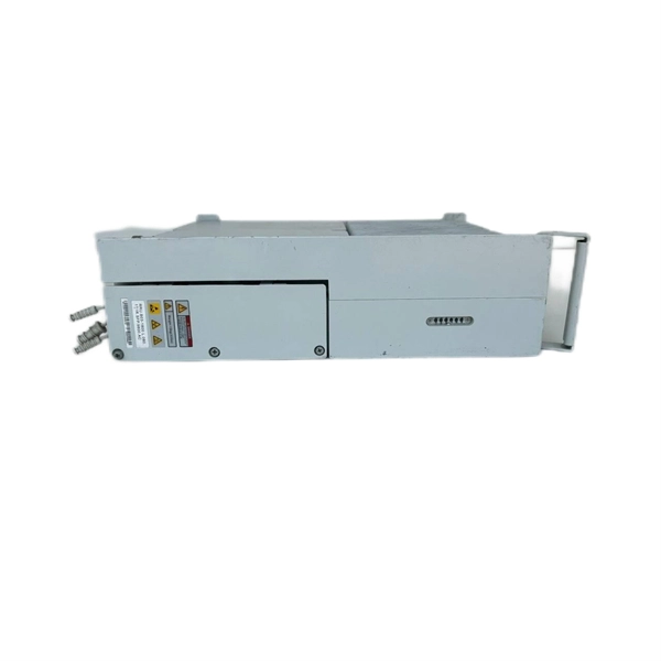
On average, you can rent a Fusion Splicer for $275/day, $773/week, $1424/month. The price of these splicers can be higher because of their mechanical complexity and ability to handle various fiber types, including large-core fibers. Hybrid splicers bring in various features that are present in both automatic splicers and manual splicers. They can be aligned by the core. Fiber optic fusion splicers are critical tools for deploying and maintaining fiber networks, with significant variations in performance, features, and pricing. This guide breaks down the key cost-influencing factors across five dimensions—splicer types, technology, performance, accessories, and. A fiber optic splicing machine is a specialized machine used to fuse two optical fibers together to form one long one. The machine, also known as a fiber optic fusion splicer, uses electricity to melt the two optic cables into one. The fiber fusion splicer conducts the fusion with high accuracy to. Check each product page for other buying options. Get reliable equipment with fast splicing times and comprehensive accessories included. It features a mini handheld design, integrated buttons and touch screen, simple operation, low.
[PDF]

The Optical Time Domain Reflectometer (OTDR) is useful for testing the integrity of fiber optic cables. It can verify splice loss, measure length and find faults. The OTDR is also commonly used to create a "picture" of fiber optic cable when it is newly installed. The Contractor tasked to perform testing or splicing on any fiber optic cable will follow these testing standards to fulfill their contractual obligations. The Contractor must utilize the correct equipment and testing techniques to gain acceptance, or the work cannot be approved. Later, comparisons can be made. For every fiber optic cable plant, you will need to test for continuity, end-to-end loss and then troubleshoot the problems. If it's a long outside plant cable with intermediate splices, you will probably want to verify the individual splices with an OTDR also, since that's the only way to make. ic system. Fiber optic testing of a newly installed system not only verifies that the system meets its design requirements, but also creates a performance baseline for all future testing and troubleshooting of t at system. What is Fiber Optic Splicing and Why is it Needed? – #1. Use and Maintain Your. This guide reveals the secrets to fusion splicing with little fluff—just proven, straightforward techniques refined from years of work in the field. The guide provides the complete workflow, covering safety precautions, tool selection, fiber preparation, fusion operation, quality control, and.
[PDF]
They directly point to the module type. Additionally, observing the color of the optical module's pull tab is a straightforward way to check it. Multimode: Pull tabs are typically black. Another very direct method is checking the. How to distinguish whether an optical fiber module is single-mode or multi-mode? Optical modules are core photoelectric conversion components in fiber-optic communication, data centers, enterprise networks, and telecom transmission systems. Correctly distinguishing single-mode and multi-mode. Understanding whether your SFP module is single-mode or multimode is crucial in network design. The choice impacts the transmission distance, data rate, and cost of your setup. Typically, single mode SFP modules are labeled as "SM" or "single mode," while multimode modules may be labeled as "MM" or "multimode. ". To determine whether the SFP module in your hand is single-mode or multi-mode, the most straightforward method is to check the color of the pull ring, for example, blue pull rings and red pull rings are single mode, and black pull rings are multimode. Multimode (MMF) SFP modules involves a cross-referencing protocol of physical bail colors, EEPROM telemetry, and wavelength specifications. Precise verification prevents "Ghost Links" and Mode Field Diameter (MFD) mismatches that degrade 800G AI fabric performance.
[PDF]

This video shows real on-site footage of electrical installation, demonstrating safe and standardized wiring methods used by professionals. But first, the rules: Turn off the power when working with electricity. Make sure the power's off using a non-contact voltage tester or multimeter. One final tip: Get into the habit of making connections in this. How to make proper & safe electrical wiring splices & connections: This article answers basic questions about how splices (connections between two or more electrical wires) are made to connect & secure electrical wires together in residential or commercial building electrical wiring systems. We. There must be a simpler way to connect the bare wire inside a duplex box. When I run a circuit into a duplex recepticle box, to an outlet, then back out again on to the next box, I wonder how to connect the bare wires together and at the same time, to the recepticle. In the past, I have cut a 6". How to properly bring bare #6 copper into service panel? I've got a small service panel in my shed (6 circuits). I drove 2 8' grounding rods outside and have routed continuous #6 bare copper into the shed. What kind of. Before installation, it's important to know what makes up a distribution box. Let's break it down into two main parts: the outer shell and the electrical parts inside. The enclosure protects the electrical components from water, dust, and damage. When choosing one, check the IP or NEMA rating.
[PDF]
This guide provides a detailed, professional procedure for installing a Residual Current Circuit Breaker (RCCB)—a device essential for protecting people from the severe danger of electric shock. The steps outlined here are fundamental to ensuring the RCCB functions. It is an electrical protective device that protects electrical circuits and devices from some electrical faults such as leakage faults, electrical shock, current unbalance due to equipment failure, etc. It works on the principle of sensing residual current which is why it is called a residual. Distribution board is a safe system designed for house or building that included protective devices, isolator switches, circuit breaker and fuses to connect safely the cables and wires to the sub circuits and final sub circuits including their associated Live (Phase) Neutral and Earth conductors. Residual-current devices, commonly referred to as RCDs, are used in many practical applications. They can be found in fuse boxes, electrical switchgears or industrial machine control systems. Therefore. To wire an RCD fuse box correctly, start by reviewing the diagram to identify each circuit and its corresponding components. Understanding the layout helps prevent mistakes and ensures safe wiring. floor in a multi storey building. The Sub distribution board is connected and supplied from the Main Distribution Board through different wires and cables rated.
[PDF]
