
In this article, you will learn the step-by-step process of testing your solar panels using a multimeter. We will cover the essential tools you need, the specific measurements to take, and how to interpret the results. A $15 multimeter and 5 minutes of testing can diagnose most solar panel problems. Measure Voc (open circuit voltage) — if it reads 0V, the panel or wiring is dead. If it reads 60–80 % of rated, a bypass diode has failed. By the end of this guide, you will be equipped with the knowledge to diagnose. Learning how to test solar panel with multimeter is useful for homeowners, technicians, farmers, and anyone using solar energy systems. A digital multimeter allows you to check voltage, current, continuity, and resistance. Fluke recommends using the Fluke 117 Electrician's Multimeter or Fluke 283 FC CAT III 1500 V Digital Multimeter to test solar modules. Here's how a technician tests solar modules with a multimeter:. A multimeter is an indispensable tool for anyone working with solar panels, allowing for accurate measurements and diagnostics. It empowers users to assess the performance, identify faults, and ensure optimal energy production. Perfect for DIY solar builders, RV owners, o. more Audio tracks for some languages.
[PDF]

The easiest way is to use the $3 "spec-grade" receptacles which come in a box instead of loose in a bin. If it's just black and white wires with a cloth or plastic covering and no ground wire you'd need a retroit grounding wire to have grounded outlets. A clearer picture of the cable entering will help. Can you post photos that show clearly where the cables enter the box at, please? @Traveler No!. The process of wiring a small breaker box, often called a subpanel, is a common task when adding power to a detached structure like a shed, garage, or a major home addition. These smaller distribution centers are designed to take power from a larger main service panel and distribute it locally to. How do I wire a mini circuit breaker distribution box that doesn't have bus bars? I have a circuit going to my shed from my house and I want to have two separate breakers inside the shed (one for outlets, one for other stuff) so I bought this from amazon (Amazon. com: 2 Way Distribution Box Circuit. In this video, we'll walk you through the process of wiring a home distribution box with a detailed connection diagram. more Welcome to our channel! In this video. Connecting a distribution box involves several steps to ensure proper electrical flow. But first, the rules: Turn off the power when working with electricity. Make sure the power's off using a non-contact voltage tester or multimeter. One final tip: Get into the habit of making connections in this.
[PDF]
Tilt sensors are devices that measure the tilt or slope of an object with respect to a reference. Fibre Bragg Grating (FBG) tilt sensors are a specific type of tilt sensor that utilizes the principle of Bragg's law in fiber optics to measure tilt angles. The tilt sensor is composed of two cylindrical floats suspended in water, connected with FBG. When the external environment causes the tilting of the sensor. Abstract—A surface-mounted tilt sensor was designed and fabricated to measure the inclination angle of engineered structures or slopes in two directions. In a FBG tilt sensor, the optical fibre is. We demonstrate a new concept for an all-fiber inclinometer based on a tapered fiber Bragg grating (tFBG) in a fiber ring laser (FRL) with the capability of measuring the tilt angle and temperature simultaneously.
[PDF]
If an EGC cable is installed in or on a cable tray, it should be bonded to each or alternate cable tray sections via grounding clamps (this is not required by the NEC® but it is a desirable practice). Cable tray may be used as the Equipment Grounding Conductor (EGC) in any installation where qualified persons will service the installed cable tray system. There is no restriction as to where the cable tray system is installed. The metal in cable trays may be used as the EGC as per the limitations. Cable tray grounding wire is the safety connection that links your electrical system's cable tray to the ground. This provides a safe path for any stray electrical currents to flow safely into the earth, avoiding damage to your equipment and reducing the risk of electric shocks. Grounding points and conductor locations must be determined. The design must comply with relevant regulations and standards.
[PDF]
On average, commercial projects range from $5,000 to $20,000 per mile underground and $40,000 to $60,000 per mile for aerial deployment. Individual business connections often cost between $15,000 and $30,000 for 100–200 network drops. Buying fiber optic installation services involves several cost components, with total price influenced by length, location, and access. The main cost drivers include trenching or aerial deployment, materials, labor hours, and any required permits. This guide presents typical price ranges in USD to. The initial cost of installing fiber optic cables can vary depending on the chosen installation method and specific project requirements. In preparing this second edition of the Fiber Deployment Cost report, Cartesian gathered inputs from a wide variety of firms building. Getting accurate cost estimates is crucial for winning fiber installation bids. Smart contractors know that underground vs aerial installation pricing varies wildly based on location and project conditions. This breakdown gives you real numbers to build better estimates. We'll show actual costs for. Home and business buyers typically see a wide range of costs for fiber optic projects, driven by distance, fiber type, conduit needs, and labor. The price can shift based on underground vs. aerial routes, equipment choices, and whether new permits are required. Some variables are less determinate.
[PDF]

This video shows you how to build a 10Gbps fiber optic network between buildings using PoE+ switches, SFP+ transceivers, and link aggregation for even higher speeds (up to 40Gbps!). Modern network infrastructure depends on fiber aggregation switches to combine several fiber optic links into one streamlined network connection. They are built to handle large amounts of data flowing through them without interruptions over long distances. more Need to transfer. With AXIS D8308 Fiber Aggregation Switch you can connect multiple Axis devices using fiber midspans over long distances. It also enables easy expansion by simply adding more fiber or network switches. Long-distance installations often require fiber optic cables to connect different sites because of. The Cisco ASR 920 Series Aggregation Services Router is a family of fixed configuration routers that enables Service Providers to provide business, residential, and mobile access services to their users. It is the Carrier Ethernet access platform providing Ethernet services. The Cisco ASR 920. This manual provides detailed instructions for the installation, operation, and maintenance of the Ubiquiti Networks UniFi Aggregation Switch, model USW-Aggregation. Fibers in these points are either spliced.
[PDF]
The good news is that network cabinet prices range from as low as $100 for basic wall-mounted units to over $3,000 for specialized outdoor models. However, understanding what drives these costs will help you make a smart buying decision. In this complete guide, we'll break down everything you need. Check each product page for other buying options. VEVOR 6U Wall Mount Network Server Cabinet, 15. 5" Deep, Server Rack Cabinet Enclosure, 200 lbs Max. 5". Explore our top-tier selection of Networking Cabinets and Racks designed to keep your IT infrastructure organized and secure. Whether you're setting up a home lab, a corporate data center, or managing network equipment for a small business, our collection offers robust and versatile solutions. Cabinets are used for storing routers, patch panels, switches and a wide variety of networking equipment and accessories. Network cabinets support large, modular network switches by providing additional space for cable management and. Network cabinets are enclosed systems designed to securely store, organize, and protect networking and IT equipment such as switches, routers, patch panels, servers, power strips, and cable management components. They allow users to secure their data and communication connections. The product will be reserved for you when.
[PDF]

Insertion loss tells you how much weaker the signal becomes after passing through the splitter. Let's say you have a laser output at 0 dBm (which is 1 milliwatt of optical power). If you use a 1×8 splitter with ~10. 5 dB of insertion loss, the power at each output would be: 0 dBm – 10. 5. Enter excess loss from the splitter datasheet for your wavelength. Add connector and splice quantities with realistic planning losses. Include any additional component losses and an engineering margin. Enable power budget to estimate received power and margin. Press Calculate to show results above. Understanding optical splitter loss isn't just about plugging numbers into a calculator. It's about knowing what factors contribute to that loss, how manufacturers specify it, and how it impacts the overall performance and reach of your network. Ignore it, and you might find your signal too weak to. Optical insertion loss refers to the signal loss resulting from the insertion of components such as connectors or splices in an optical fiber system. Common ratios: For cascades, add losses and validate margin using the Optical Budget tool. This Fiber Optic Splitter Insertion Loss is the splitter devices loss, Considering fiber connectors or connectors+adapter insertion loss in LGX, The fiber splitter IL would be a little bigger. To make clear the basic ftth fiber splitter loss in performance, You can refer to the below loss chart.
[PDF]
Dubai Electricity and Water Authority (DEWA) extended over 364 kilometres of Fibre Optic (FO) ducts across different areas in Dubai in 2023. This has increased the total length of these cable ducts to 3,998 kilometres, a 10% increase compared to 2022. Fibre refers to a type of internet connectivity where information is transmitted via fibre optic cables. This is in line with DEWA's efforts to build a. As w. media's Global Editor-in-Chief, Grey covers the cloud and data center industry and connectivity ecosystem across APAC and EMEA. In a career spanning over two decades, Grey has dabbled in television, print and online journalism, covering a variety of beats including human rights, health. Please try refreshing the page. Visualize the growth of global connectivity. Flexible No Contract Option At AED 2250 / Month Best fiber internet deals in Dubai: du's cable plans deliver 250Mbps to 1Gbps. Includes free smart router and 24/7 premium support. We do have Etisalat approved and DU approved brands in Fiber optic brand with us. We keep complete Stock Fiber Optic Products from 2 Core FTTH cables to 48Core cables in Single mode and Multimode ( OM2, OM3 and OM4).
[PDF]

An ideal optical splitter will distribute the light power according to mathematical principle. This is because each of the 8 output ports of the splitter will receive only one-eighth of the. Thorlabs' Single Mode 1x8 Fiber Optic Planar Lightwave Circuit (PLC) Splitters allow a user to split a single input signal evenly into eight output signals, which is ideal for passive optical networks (PON) and other high-channel-count applications. 1×8 splitter means it takes one input fiber and splits the signal into eight outputs. It doesn't need power — it's passive! Great for sharing one signal with many devices, like in FTTH (Fiber To The Home) networks. But light doesn't just split for free. Sharing means each output gets less than the. If we operate with absolute gains measured in relation to 1 milliwatt (mW), they are expressed in dBm, and are calculated as follows: Power Level (dBm) = 10 lg ( mW / 1 ) For “household” needs, in order not to calculate mW to dBm and vice versa every time, here's a ready-made correspondence table:. For instance, a 1:8 splitter ratio signifies an equal distribution of incoming optical power among eight output ports, with each port receiving 1/8th of the total power. It has one input port and eight output ports, making it ideal for applications where a signal needs to be.
[PDF]
Picking up the best router for fiber internet isn't just about going to the market and choosing one of the best wireless routers. Instead, you need to carefully look at its specs, performance, and the type of securit.
[PDF]
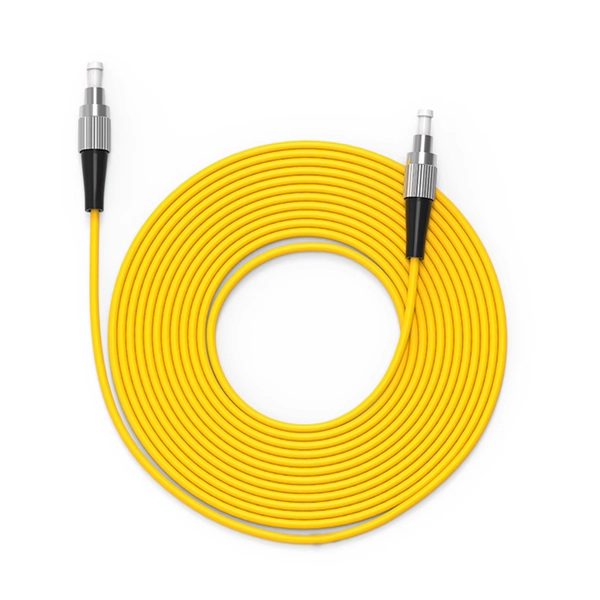
In this informative guide, we'll walk you through the step-by-step process of stripping and preparing fibre optic cable for termination, covering techniques, tools, and best practices to help you achieve successful terminations in your fibre optic installations. Strip the jacket and buffer: Using a fiber optic cable stripper, remove the outer jacket and buffer tubes from the cable. Make sure to strip the appropriate length, as specified by the manufacturer. Be cautious not to damage the fibers during this process. Cleave and cut the fibers: After. In this instructional video, Bob Licari, Test Equipment Product Manager, demonstrates a simple way to strip optical fiber. more Audio tracks for some languages were automatically generated. Eventually, this imperfection can initiate a crack when the. It is impossible to work in fiber optics without having a good working knowledge about cables and skills in pulling, placing and preparing cables for termination and splicing. Properly stripping the cable and preparing the fibre ends ensures a clean and secure connection, leading to optimal signal transmission and network performance. Terminating fiber optic cables essentially means putting connectors on fiber optic cable so that you can connect the cable to various devices or network components. Think of it as the equivalent of connecting the dots in a complex puzzle; without proper termination, the whole system can break down.
[PDF]

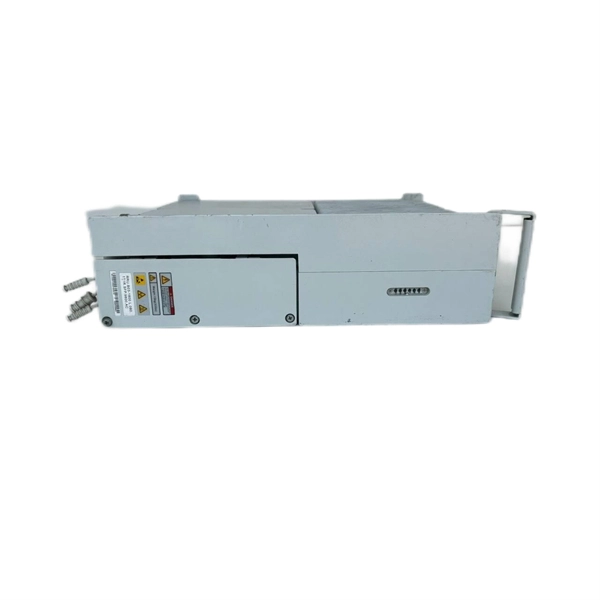
It transforms high volumes of electrical signals into optical signals for transmission over fiber cables, or reverses the process at the receiving end. Think of it like a Type-C to USB adapter in everyday tech—its core function is seamless conversion between electrical and optical. Optical modules are compact devices that convert electrical signals into optical signals and vice versa. They are used in fiber optic communication systems to transmit data over long distances with minimal loss and interference. These modules typically consist of a laser or LED transmitter, a. In the world of fiber optic communications, optical transceiver modules play a pivotal role as interfaces that convert electrical signals to optical signals and vice versa. An optical module works at the physical layer of the OSI model and is one of the core components in the fiber communication. The frequency response characterization of these electrical-to-optical (E/O, modulators sometimes integrated with lasers) and optical-to-electrical (O/E, photo detectors and receivers) converters can be important in terms of such parameters as bandwidth, flatness, phase linearity and group delay. The optical module serves as a crucial component in optical fiber communication systems, operating at the physical layer, which is the lowest layer in the OSI model. Among various optical module form factors, SFP (Small Form-Factor Pluggable).
[PDF]


