
In this article, you will learn the step-by-step process of testing your solar panels using a multimeter. We will cover the essential tools you need, the specific measurements to take, and how to interpret the results. A $15 multimeter and 5 minutes of testing can diagnose most solar panel problems. Measure Voc (open circuit voltage) — if it reads 0V, the panel or wiring is dead. If it reads 60–80 % of rated, a bypass diode has failed. By the end of this guide, you will be equipped with the knowledge to diagnose. Learning how to test solar panel with multimeter is useful for homeowners, technicians, farmers, and anyone using solar energy systems. A digital multimeter allows you to check voltage, current, continuity, and resistance. Fluke recommends using the Fluke 117 Electrician's Multimeter or Fluke 283 FC CAT III 1500 V Digital Multimeter to test solar modules. Here's how a technician tests solar modules with a multimeter:. A multimeter is an indispensable tool for anyone working with solar panels, allowing for accurate measurements and diagnostics. It empowers users to assess the performance, identify faults, and ensure optimal energy production. Perfect for DIY solar builders, RV owners, o. more Audio tracks for some languages.
[PDF]

Connect all three phases and the neutral wire to the input of the residual-current device. An overcurrent circuit breaker is connected at the output to each phase. It is an electrical protective device that protects electrical circuits and devices from some electrical faults such as leakage faults, electrical shock, current unbalance due to equipment failure, etc. It works on the principle of sensing residual current which is why it is called a residual. Distribution board is a safe system designed for house or building that included protective devices, isolatorswitches, circuit breaker and fuses to connect safely the cables and wires to the sub circuits and final sub circuits including their associated Live (Phase) Neutral and Earth conductors. A residual-current device (RCD), protects the user of the installation against electric shock. Therefore, not only the efficiency and reliability, but also the proper connection of this device is important. Make sure you have watched the linked video below on how to strip and prepare wires and cables for termination before you do any wiring:. more Audio tracks for some languages were automatically generated. This guide provides a detailed, professional procedure for installing a Residual Current Circuit Breaker (RCCB)—a device essential for protecting people from the severe danger of electric shock. The steps outlined here are fundamental to ensuring the RCCB functions correctly as a life-saving.
[PDF]
Testing solar panels is easy with a multimeter! To test the current, simply connect the multimeter to the panel's output. Set it to read DC current. To test voltage, set your multimeter to. A $15 multimeter and 5 minutes of testing can diagnose most solar panel problems. Measure Voc (open circuit voltage) — if it reads 0V, the panel or wiring is dead. If it reads 60–80 % of rated, a bypass diode has failed. If Voc is normal but the system is not producing, the problem is downstream. Solar panels are usually tested under standard conditions using a light source that mimics the light from the sun on a clear day. You can use the following method if you want to test your solar panel under standard conditions. We will cover the. A multimeter is a tool that measures the voltage, current, and resistance of an electrical circuit. Fluke recommends using the Fluke 117 Electrician's Multimeter or Fluke 283 FC CAT III 1500 V Digital Multimeter to test solar modules. This helps you spot issues early and keep your system running efficiently. By the end of this guide, you will be equipped with the knowledge to diagnose.
[PDF]
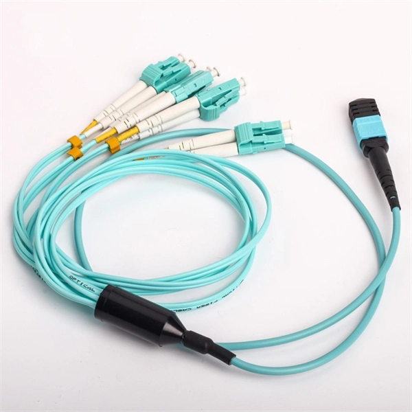
In this video, Joe would display how to connect SC fiber optical connector in 2 minutes. Related product:. Step 4 i s to affix the fiber to the connector. The fiber should be inserted into the connector until it is flush with the ferrule end. Step 5: Let the epoxy cure. These connectors ensure high-quality signal transmission, which is essential for reliable internet and communication services. SC APC connectors offer superior optical. There are many types of fiber optic connectors, including SC, LC, FC, ST, D4, MU, MT/MPO, etc. These connectors can be divided into single-mode and multi-mode fiber optic connectors according to their structure and purpose. To learn more about the types of fiber optic connectors, click here: Types. The global SC fiber optic connector market is valued at approximately 903 million USD in 2025 and is projected to grow steadily, which reflects its continuing role as a standard interface in fiber infrastructure, including plant backbones and industrial automation links, according to SC connector. SC fiber connectors, or Subscriber Connectors, are widely used in telecom and networking for their strong performance and easy handling. They're known for a secure push-pull connection that's quick to insert and remove.
[PDF]

The process involves a combination of national infrastructure, local engineering, and property-level setup. In this guide, we'll break down the fiber installation process from start to. This guide walks you through the complete fiber installation process, from checking availability to optimizing your Wi-Fi network performance. Fiber transmits data using light signals through glass strands, delivering faster speeds and lower latency than cable or DSL connections that rely on. In this article we'll break down how fiber internet is installed - from the network fiber drop outside your house to the in-home setup with your router and gateway - and what you should expect at each stage. Fiber optic internet is generally installed in the following 5 steps, which we'll dive. Want lightning-fast internet at home? Fiber optic installation is the way to go! It's super reliable and perfect for streaming, gaming, or using multiple devices. This guide breaks down the process in easy steps so you know what to expect. BCS Consultants, a trusted fiber optic installation company based in California, provides end-to-end fiber optic services, including expert planning. However, setting up a fiber optic connection to your router can seem daunting if you're unfamiliar with the process. In this guide, we'll walk you through how to connect a fiber optic cable to a router safely and efficiently. Why Use Fiber Optic Internet? Before diving into the setup, let's quickly.
[PDF]

The Optical Time Domain Reflectometer (OTDR) is useful for testing the integrity of fiber optic cables. It can verify splice loss, measure length and find faults. The OTDR is also commonly used to create a "picture" of fiber optic cable when it is newly installed. The Contractor tasked to perform testing or splicing on any fiber optic cable will follow these testing standards to fulfill their contractual obligations. The Contractor must utilize the correct equipment and testing techniques to gain acceptance, or the work cannot be approved. Later, comparisons can be made. For every fiber optic cable plant, you will need to test for continuity, end-to-end loss and then troubleshoot the problems. If it's a long outside plant cable with intermediate splices, you will probably want to verify the individual splices with an OTDR also, since that's the only way to make. ic system. Fiber optic testing of a newly installed system not only verifies that the system meets its design requirements, but also creates a performance baseline for all future testing and troubleshooting of t at system. What is Fiber Optic Splicing and Why is it Needed? – #1. Use and Maintain Your. This guide reveals the secrets to fusion splicing with little fluff—just proven, straightforward techniques refined from years of work in the field. The guide provides the complete workflow, covering safety precautions, tool selection, fiber preparation, fusion operation, quality control, and.
[PDF]
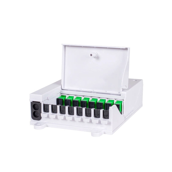
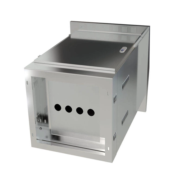
We manufacture and stock Distributions Boxes in various sizes from 3 outlets to 14 outlets:. We manufacture and stock Distributions Boxes in various sizes from 3 outlets to 14 outlets:. BOX WALL FS NEMA RATE SC APC 24 PORT Outdoor Wall Box FieldSmart Wall Mount Outdoor Rated (24 port capacity) panel panel, 24 Singlemode SC/APC Ports, loaded with tight buffer singlemode pigtail in Clearview patch and splice tight buffer singlemode pigtail in Clearview patch and splice Cassette. Jensen's wastewater distribution boxes offer a comprehensive range of reliable solutions for efficient wastewater distribution in septic systems. Today, electrical systems are essential for homes and industries. But what exactly is a power distribution box, and why is it so essential in our daily lives? The DB panel board controls the flow of electricity. This increases stopping power and steering responsiveness, decreases trailer sway, and improves overall stability. This is particularly useful when towing heavy loads like RVs, which can otherwise cause the tow vehicle to become.
[PDF]

The setting value can be finely adjusted manually. Press and hold the and buttons simultaneously for three seconds. Use the to select "rSt", then press the button. Settings are summarized in "Basic" and "Advanced" categories. Providing quick solutions for every scenario. In cases where more advanced features or troubleshooting is necessary, the "Advanced". This video covers how to setup and configure the Wenglor OPT2041 Fiber Optic Sensor from AutomationDirect. **Please check our website for our most up-to-date product pricing and availability. This sensor works with both Plastic and Glass fibers. Keep in mind that the color and reflectivity of the. The KEYENCE FS-N10 Fiber Sensor is a versatile and reliable device used for detecting objects. This sensor uses a fiber optic cable to transmit and receive light, allowing for accurate and precise detection in a variety of applications. The FS-N10 series is capable of detecting objects of different. Fiber optic Sensors; How to program Keyence Fiber optics amplifier from EMI Documentation can be found here:. This is the SET push button; this is used to calibrate the sensitivity.
[PDF]

In this step-by-step tutorial, learn how to splice fiber optic cables like a pro — perfect for telecom technicians, network engineers, and field techs. more 🔧 Watch a real-time fiber optic splicing demo in action!. Fiber cable splicing is a critical step in building reliable fiber optic networks. Whether in data centers, telecom rooms, or outdoor FTTx deployments, proper splicing inside a fiber enclosure ensures low signal loss, long-term stability, and easy maintenance. This guide explains what fiber cable. In this guide, we cover the basics of fiber optic splicing, how to perform splicing using two different methods, and finally some best practices to perform good fiber splicing. What is Fiber Optic Splicing and Why is it Needed? – #1. Whether repairing a broken cable or extending a fiber run, fiber optic splicing ensures light signals travel. Regardless of your level of experience, creating high-quality, high-performance fiber optic networks requires developing your skills in fusion splicing. This guide reveals the secrets to fusion splicing with little fluff—just proven, straightforward techniques refined from years of work in the.
[PDF]

When it comes to testing fiber optic cables, a Visual Fault Locator (VFL) is an essential tool in your toolkit. A VFL is used to detect faults, breaks, or bends in fiber optic cables by emitting a bright red light that is visible even through the fiber's jacket. It's a cost-effective and. A Visual Fault Locator which can be also called visual fault identifier (VFI), fiber fault locator, fiber fault detector, etc., is a visible red laser light designed to inject visible red light energy into an optical fiber. Using a VFL to diagnose issues can save time and cost when diagnosing an. A visual fault locator is a compact, handheld device that emits a visible light beam, typically in the red wavelength range, through a fiber optic cable. It works by injecting a visible red laser light into the fiber, which can be seen through the jacket or at the end of the cable. If the light doesn't come out the other side, there might be a problem. You. And in the end we will show you how to use an old cell phone's camera to detect light in a fiber optic system. It uses a bright incandescent bulb or visible LED source to.
[PDF]

Connect the phase and neutral wires from the input power supply to the input of the Main MCB. They can correct voltage, but they have no effect on power factor. They are installed in series between the Source and Load. They are a voltage source, they add or subtract. When you're towing something much heavier or lighter than usual, you'll need to make adjustments to your weight-distribution hitch. Fortunately, adjusting a weight-distribution hitch for safe towing is fairly straightforward. But if you need more guidance on how to connect your hitch in the first. This green leaf icon designates information specifically for Vista® Green Underground Distribution Switchgear that uses a CO mix insulating gas. Unless otherwise designated, instructions provided apply to all manual 2 Vista switchgear products. Take the appropriate rating of MCB and RCCB as per your load requirements. Identify the Input and Output sides of the MCBs and RCCBs. If you use. Use the Exchange admin center (EAC) or Exchange Online PowerShell to create, modify, or remove distribution lists in your Exchange Online organization. Exchange Online supports four types of groups that can be used to distribute messages: Distributions lists that can be used only to distribute. This bulletin contains instructions for installing Square D brand I-Line circuit breaker power distribution panelboards.
[PDF]

These numerical codes, ranging from 1 to 99, uniquely identify the functions of protective relays, associated devices, and control equipment in electrical power systems. In electric power systems and industrial automation, ANSI Device Numbers can be used to identify equipment and devices in a system such as relays, circuit breakers, or instruments. The device numbers are enumerated in ANSI / IEEE Standard C37. 2 Standard for Electrical Power System Device Function. According to the ANSI/IEEE standards, device function numbers are crucial identifiers in power system protection and control engineering. ANSI IEEE Standard Device Numbers are below: (the more commonly used ones are in bold) 86T is a Lockout Relay for a. The widely used United Sates standard ANSI/IEEE C37. Even in those parts of the world where IEC standards are predominate, the use of ANSI numbering. For power grid systems, ANSI and IEEE functional number codes dictate the use and restrictions of both the devices themselves, as well as the functions of those devices within the scope of a circuit. These devices include switches, disconnects, circuit breakers, generators, and motors. Instead of verbal descriptions, we use numbers to describe the functions of a relay. Why use numbers instead of words? Efficiency.
[PDF]

The optical power meter is similar to the voltohmmeter in application but measures the optical resistance (losses measured in dBm or dBM) of a cable before and after installation and provides a comparative analysis of the splices. The range of the meter is adjustable. Regularly testing fiber optic cables helps minimize network downtime, lengthens the network's longevity, reduces maintenance requirements, and helps support network reconfiguration and upgrades. These factors significantly add to the fiber optic network's long-term performance, manageability, and. Several types of tests are commonly conducted to assess and maintain the health of fiber optic networks. Continuity testing verifies that the fiber is intact and that light can pass through from one end to the other without any blockages. These test procedures assess the physical and functional qualities of fiber optic cables, connectors, and the network as a whole. Key tests include: Effective fiber testing utilizes advanced tools such as Optical. One way to test a splice is to use an Optical Power Meter. As the components like fiber, connectors, splices, LED or laser sources, detectors and receivers are being developed, testing confirms their performance specifications and helps. Regular testing of fiber optic cables is not just a preventive measure; it's an investment in the longevity and efficiency of your network. By identifying potential issues early, you can enhance.
[PDF]