
Just count the number wire leads coming from the connector and scroll to the section with that number. Executive Summary: A fiber optic pigtail is one of the most commonly specified yet least understood components in structured cabling. Get the wrong connector type, the wrong polish, or skip proper fusion splicing technique—and you're looking at elevated signal loss, increased back reflection, and a. Terminal Release Tools RTTP #s: NUD900-001, NUD900-002, NUD900-003 and NUD105-R025E Flex Probe Kit are available through RTTP. 2ND GENERATION - EXPANDED TO INCLUDE 8 AWG APPLICATIONS! Ford has identified through testing and engineering analysis, the optimal repair procedure for solderless wire. It includes an identification guide with images of various connectors and kits, highlighting their use in vehicle electrical repairs. The document details specific toolkits such as the Ford Flex Probe Kit and the Wire Splice Tool Kit, designed for repairing electrical wiring harnesses. Match the connector in the picture. They contain 5 uninsulated butt splices, 5 pieces of dual wall adhesive-lined heat shrinkable tubing, and the new instruction sheet detailing the approved wire splice procedure as defined by Ford Motor Company. Expanded wire gauge applications for these splices can be found in Technical Service.
[PDF]
Testing solar panels is easy with a multimeter! To test the current, simply connect the multimeter to the panel's output. Set it to read DC current. To test voltage, set your multimeter to. A $15 multimeter and 5 minutes of testing can diagnose most solar panel problems. Measure Voc (open circuit voltage) — if it reads 0V, the panel or wiring is dead. If it reads 60–80 % of rated, a bypass diode has failed. If Voc is normal but the system is not producing, the problem is downstream. Solar panels are usually tested under standard conditions using a light source that mimics the light from the sun on a clear day. You can use the following method if you want to test your solar panel under standard conditions. We will cover the. A multimeter is a tool that measures the voltage, current, and resistance of an electrical circuit. Fluke recommends using the Fluke 117 Electrician's Multimeter or Fluke 283 FC CAT III 1500 V Digital Multimeter to test solar modules. This helps you spot issues early and keep your system running efficiently. By the end of this guide, you will be equipped with the knowledge to diagnose.
[PDF]

In this article, you will learn the step-by-step process of testing your solar panels using a multimeter. We will cover the essential tools you need, the specific measurements to take, and how to interpret the results. A $15 multimeter and 5 minutes of testing can diagnose most solar panel problems. Measure Voc (open circuit voltage) — if it reads 0V, the panel or wiring is dead. If it reads 60–80 % of rated, a bypass diode has failed. By the end of this guide, you will be equipped with the knowledge to diagnose. Learning how to test solar panel with multimeter is useful for homeowners, technicians, farmers, and anyone using solar energy systems. A digital multimeter allows you to check voltage, current, continuity, and resistance. Fluke recommends using the Fluke 117 Electrician's Multimeter or Fluke 283 FC CAT III 1500 V Digital Multimeter to test solar modules. Here's how a technician tests solar modules with a multimeter:. A multimeter is an indispensable tool for anyone working with solar panels, allowing for accurate measurements and diagnostics. It empowers users to assess the performance, identify faults, and ensure optimal energy production. Perfect for DIY solar builders, RV owners, o. more Audio tracks for some languages.
[PDF]

When it comes to testing fiber optic cables, a Visual Fault Locator (VFL) is an essential tool in your toolkit. A VFL is used to detect faults, breaks, or bends in fiber optic cables by emitting a bright red light that is visible even through the fiber's jacket. Let's dive into everything you need to know about mastering VFLs. It's a cost-effective and. Visual Fault Locator (VFL) testing is one of the most fundamental inspection methods used in FTTH, ODN, and data center environments. A VFL emits a visible red laser (typically 650 nm) that travels along the fiber core and leaks out at points of excessive loss, fiber breaks, or microbends. Although. The Fiber Visual Fault Locator Kit is an essential tool for network technicians and engineers; it provides an accurate and quick method of finding such problems as breaks, bends or faults that may affect the network's operation. It works by injecting a visible red laser light (usually in the 650nm wavelength) into the fiber. When the light encounters a fault, such as a break, bend, or bad splice, it leaks out of the fiber, making the. Conducting efficient, repeatable fiber optic cable certification requires an array of specialized test equipment: Optical Loss Test Set (OLTS) – Integrates adjustable light source and power meter for efficient, Tier-1 insertion loss testing. Visual Fault Locators – Handheld devices projecting.
[PDF]
As light in fibers often does not have a well defined polarization state, it is important that a fiber-optic attenuator exhibits only a minimum amount of polarization dependence. Generally, the obtained insertion loss has some dependence on the optical wavelength. Some attenuators have a relatively strong wavelength dependence and are made for working in narrow wavelength regions, e.g. with a bandwidth of only 20 nm around a center wavelength of 1550 nm. Others are optimized for a weaker wavelength dependence, making them u. For single-mode devices, the insertion loss can not depend on the direction of propagation, as long as no non-reciprocal parts are used, as e.g. in a Faraday isolator. For multimode devices, however, some loss difference is possible in conjunction with a mode dependence. For many applications, it will not be a problem if the obtained insertion loss slightly deviates from the specification (e.g. by 1 dB), or if it slightly changes over time. Example cases, however, one may require a higher precision. Most fiber-optic attenuators exhibit a relatively high return loss (at least several dozens of decibels), i.e., there is not much light which is reflected back into the input fiber. For some sensitive applications, e.g. when using an attenuator before or after a high-gain fiber amplifier, one may have two use attenuators with particularly high retu.
[PDF]

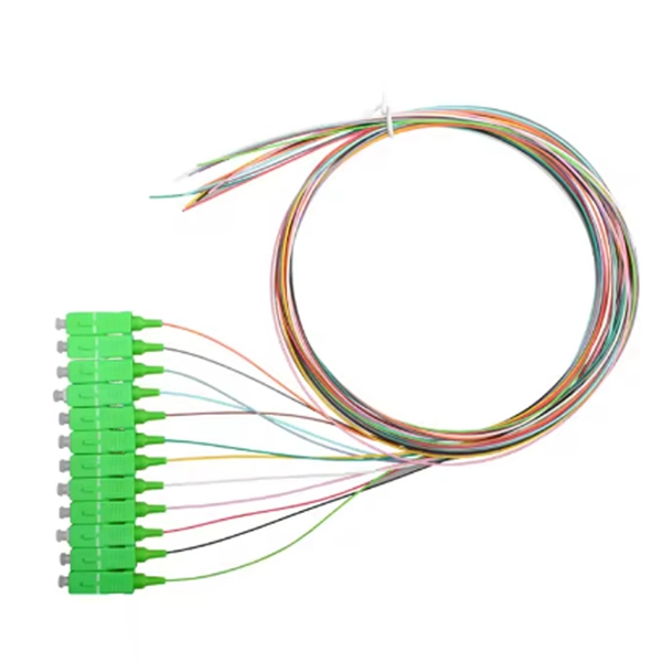
Explore 39 top manufacturers and suppliers of Fiber Optic Patch Cords in our comprehensive photonics buyers' guide. Manufacturer of fiber optics and related instrumentation, components, and assemblies for spectroscopic and laser delivery applications. Fiberopticpatchcords are also offered. Packaging, prototyping, engineering drawing, labelling, and kitting are offered as secondary services. Serves electronics. In the United States, there are many professional network patch cord manufacturers that can manufacture and supply high-quality Category 5, Category 6, and Category 6A RJ45 patch cables. But it's a bit difficult to find the best one with the most competitive price. To help you find the best. This section provides an overview for fiber patch cable as well as their applications and principles. CBO GmbH. fiber optic patch cord manufacturer should be selected by connector type, single mode or multimode fiber, polish type, cable diameter, jacket material, length, insertion loss requirement, labeling, packaging, and quantity. Products include fiber optic assemblies for. This report studies the Optical Fiber Patch Cord market, also known as fiber optic patch cable or fiber jumper, it is an Optical Fiber Patch Cord is a fiber optic cable capped at either end with connectors that allow it to be rapidly and conveniently connected to CATV, an optical switch or other.
[PDF]
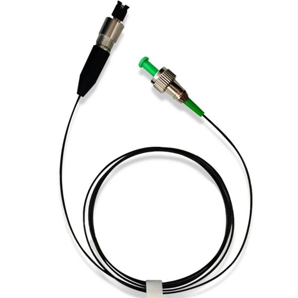
In this video, Joe would display how to connect SC fiber optical connector in 2 minutes. Related product:. Step 4 i s to affix the fiber to the connector. The fiber should be inserted into the connector until it is flush with the ferrule end. Step 5: Let the epoxy cure. These connectors ensure high-quality signal transmission, which is essential for reliable internet and communication services. SC APC connectors offer superior optical. There are many types of fiber optic connectors, including SC, LC, FC, ST, D4, MU, MT/MPO, etc. These connectors can be divided into single-mode and multi-mode fiber optic connectors according to their structure and purpose. To learn more about the types of fiber optic connectors, click here: Types. The global SC fiber optic connector market is valued at approximately 903 million USD in 2025 and is projected to grow steadily, which reflects its continuing role as a standard interface in fiber infrastructure, including plant backbones and industrial automation links, according to SC connector. SC fiber connectors, or Subscriber Connectors, are widely used in telecom and networking for their strong performance and easy handling. They're known for a secure push-pull connection that's quick to insert and remove.
[PDF]

High Initial Investment Costs:The transition to LED and smart lighting systems involves substantial upfront costs, estimated at around $1. 5 billion for large-scale implementations in South Korea. The South Korea Lighting Distribution Cabinet Market was valued at 8. 04 billion in 2025 and is projected to grow at a CAGR of 6. 17% from 2026 to 2033, reaching an estimated 12. This expansion is fueled by rising demand across industrial, commercial, and technology-driven. The South Korea LED and Smart City Lighting Market, valued at USD 1. 7 billion, is growing due to demand for IoT-enabled systems, energy savings, and urban development in cities like Seoul and Busan. 7 billion, based on a. Market Forecast By Offering (Hardware, Software, Services), By Installation Type (New Installations, Retrofit Installations), By End Use Application (Indoor, Outdoor), By Communication Technology (Wired, Wireless) And Competitive Landscape The South Korea smart lighting market is experiencing. Find local businesses, view maps and get driving directions in Google Maps. Market segmentation highlights a preference for hanging cabinets, likely due to space efficiency. 15 million by 2026–31, driven by smart city pilots and commercial modernization. The evolution of South Korea's smart lighting market is rooted in the country's early nationwide commitment to digital infrastructure.
[PDF]
The detailed steps outlined herein provide a comprehensive understanding of optical attenuator installation and adjustment. Proper execution enhances the efficiency and stability of the attenuators and the overall communication system. Fibre optic attenuators, also called optical attenuators, are passive devices used to reduce the power level of an optical signal. Assemble all necessary tools and equipment, such as a fiber cleaver, fusion splicer, optical power meter, and connector cleaning tools. These are the cornerstones of a seamless installation. Equally. Having a deep understanding of how to select a fiber optic attenuator, regardless of the type—fixed or variable—and the type of fiber and connector is critical to the durability and maintainability of a reliable network. Taking optical power measurements before installation of a fiber optic. Optical Signal Attenuation is the single greatest factor limiting the distance and performance of your network. Understanding it is crucial for anyone involved in data centers, telecommunications, or enterprise networking. In this. 📦 For purchasing, use the RP Photonics Buyer's Guide for optical attenuators. It provides an expert-curated supplier directory, buyer-focused technical background information, and structured selection criteria to support professional procurement decisions. Optical attenuators are devices that.
[PDF]
An optical network is a communication system that leverages light to convey information across distances, encoding data into rapid flashes of light instead of relying on electrical voltage changes. At the heart of this ecosystem lies the Optical Transport Network (OTN) — a framework defined by the ITU-T (notably G. 709) that has become the foundation for modern optical communications. This method allows engineers to manage the exponential growth in global data traffic generated by. A passive optical network (PON) is a system commonly used by telecommunications network providers that brings fiber optic cabling and signals all or most of the way to the end user. Depending on where the PON terminates, the system can be described as fiber to the curb, fiber to the building or. An Optical Transport Network (OTN) is a transmission network based on wavelength division multiplexing (WDM) technology. It is a specific type of transmission network that transmits data and manages it using optical signals. OTN is built on a series of protocols, including G. It is designed to provide a high-speed, scalable, and reliable infrastructure for the transmission of data between different network nodes. While there are many subtle differences, a clear distinction between active optical networking and PON topology is PON's use of a.
[PDF]

Align the fiber with the connector's guide. Ensure the fiber does not bend or twist during insertion. A proper fit prevents signal loss and enhances performance. Secure the connection using the fast connector's. Optical fiber fast connectors, also known as cold connectors, are becoming increasingly popular due to their ease of use and quick installation. Unlike traditional fiber connectors that require epoxy and polishing, fast connectors use a mechanical splice to join the fibers. In this article, we will. At the heart of any robust fiber optic network lies a crucial process: Preparing a fiber cable for termination of a connector or splice. Two types of splices are used in fiber optic cabling one is Mechanical the other is Fusion. Whether you're installing a new network, expanding an existing one, or. Optic Fiber cleaving, and mechanical splicing through very simple processes in this short series of videos. Thank you for supporting us by viewing our content. Doubts and suggestions? Leave us you. more Audio tracks for some languages were automatically generated. The primary purpose of a fast connector is to ensure a stable and reliable link. Connecting a fiber optic cable to a connector is a precise task that requires careful attention to detail, as well as some specialized tools and equipment. These terminations must be of the right style, installed in a.
[PDF]
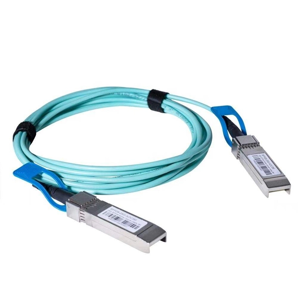
They directly point to the module type. Additionally, observing the color of the optical module's pull tab is a straightforward way to check it. Multimode: Pull tabs are typically black. Another very direct method is checking the. How to distinguish whether an optical fiber module is single-mode or multi-mode? Optical modules are core photoelectric conversion components in fiber-optic communication, data centers, enterprise networks, and telecom transmission systems. Correctly distinguishing single-mode and multi-mode. Understanding whether your SFP module is single-mode or multimode is crucial in network design. The choice impacts the transmission distance, data rate, and cost of your setup. Typically, single mode SFP modules are labeled as "SM" or "single mode," while multimode modules may be labeled as "MM" or "multimode. ". To determine whether the SFP module in your hand is single-mode or multi-mode, the most straightforward method is to check the color of the pull ring, for example, blue pull rings and red pull rings are single mode, and black pull rings are multimode. Multimode (MMF) SFP modules involves a cross-referencing protocol of physical bail colors, EEPROM telemetry, and wavelength specifications. Precise verification prevents "Ghost Links" and Mode Field Diameter (MFD) mismatches that degrade 800G AI fabric performance.
[PDF]

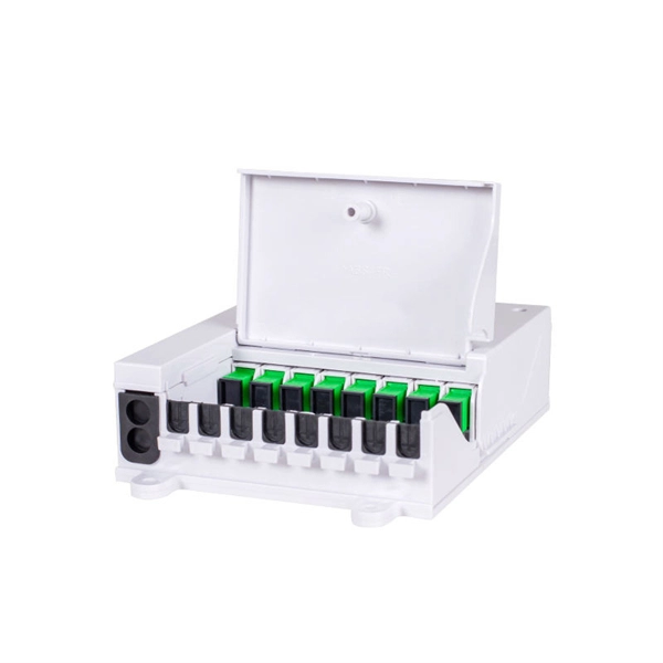
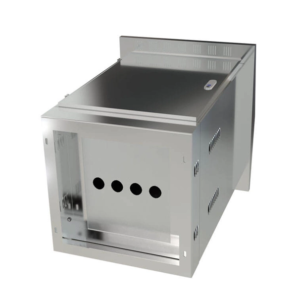
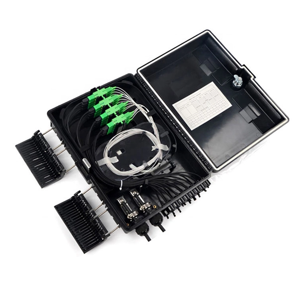
This video shows real on-site footage of electrical installation, demonstrating safe and standardized wiring methods used by professionals. But first, the rules: Turn off the power when working with electricity. Make sure the power's off using a non-contact voltage tester or multimeter. One final tip: Get into the habit of making connections in this. How to make proper & safe electrical wiring splices & connections: This article answers basic questions about how splices (connections between two or more electrical wires) are made to connect & secure electrical wires together in residential or commercial building electrical wiring systems. We. There must be a simpler way to connect the bare wire inside a duplex box. When I run a circuit into a duplex recepticle box, to an outlet, then back out again on to the next box, I wonder how to connect the bare wires together and at the same time, to the recepticle. In the past, I have cut a 6". How to properly bring bare #6 copper into service panel? I've got a small service panel in my shed (6 circuits). I drove 2 8' grounding rods outside and have routed continuous #6 bare copper into the shed. What kind of. Before installation, it's important to know what makes up a distribution box. Let's break it down into two main parts: the outer shell and the electrical parts inside. The enclosure protects the electrical components from water, dust, and damage. When choosing one, check the IP or NEMA rating.
[PDF]