In today's data-driven world, high-speed optical modules (e., 100G/400G/800G) are the backbone of modern networks, enabling ultra-low latency and massive bandwidth for data centers, telecom, and enterprise applications. However, their performance hinges on proper deployment. nd Latency variation are very important in applications requiring accurate timing (e (PAM-4 or Coherent), require complex digital signal processors (DSPs) in optic itional EEPROM data content for propagation del ss C. 2” pluggable : 2% of the cTE budget ITU-T G. 2 allocated for Class C A. 20”. This article helps trading engineers and network architects select an ultra low latency SFP that fits 10G/1G optics needs while minimizing added propagation and serialization delay. A solution for accurately measuring the Latency of PAM4 optical modules is required. Potential source of time error in complex digital parts of pluggables. Higher bit rates (50 Gb/s and higher) and. Transceiver latency is a key spec in enterprise fiber optic networks especially in financial institutions. It is the one of the few variables that can be optimized since fiber path delay is fixed. However, their performance hinges on proper deployment and maintenance.
[PDF]
They directly point to the module type. Additionally, observing the color of the optical module's pull tab is a straightforward way to check it. Multimode: Pull tabs are typically black. Another very direct method is checking the. How to distinguish whether an optical fiber module is single-mode or multi-mode? Optical modules are core photoelectric conversion components in fiber-optic communication, data centers, enterprise networks, and telecom transmission systems. Correctly distinguishing single-mode and multi-mode. Understanding whether your SFP module is single-mode or multimode is crucial in network design. The choice impacts the transmission distance, data rate, and cost of your setup. Typically, single mode SFP modules are labeled as "SM" or "single mode," while multimode modules may be labeled as "MM" or "multimode. ". To determine whether the SFP module in your hand is single-mode or multi-mode, the most straightforward method is to check the color of the pull ring, for example, blue pull rings and red pull rings are single mode, and black pull rings are multimode. Multimode (MMF) SFP modules involves a cross-referencing protocol of physical bail colors, EEPROM telemetry, and wavelength specifications. Precise verification prevents "Ghost Links" and Mode Field Diameter (MFD) mismatches that degrade 800G AI fabric performance.
[PDF]
Check the diagnostic information, which shows that the received optical power is low, with a threshold of -3 to -23. 01, currently at -22. Once it exceeds the threshold, an alarm will be triggered. Troubleshoot the link, and if the link is normal, replace the optical module. The receive power of an optical module is too low. Indicates the MIB object ID of the alarm. The device management or driver software has a bug. Use an optical power meter to check whether the transmit optical power of the optical module is normal. Remove and. When an optical module is running on a switch, it is often necessary to read its internal information to check the operating status, including link status, real-time Tx/Rx optical power, and temperature. Verifying module identification also helps confirm coding compatibility between the module and. The optical module on the port generates an alarm. Built into modern SFP/SFP+/ SFP28 /QSFP family modules and standardized by SFF-8472, DDM/DOM exposes real-time values for the module's temperature, supply. This chapter gives a description, severity, and troubleshooting procedure for each commonly encountered Cisco NCS 1001 alarm and condition. When an alarm is raised, refer to its clearing procedure. Default Severity: Critical (CR), Service Affecting (SA) Logical Object: EQUIPMENT The 0/PM [0|1] Unit.
[PDF]
Optical modules —including SFP, QSFP, and CWDM series —serve as the core components enabling this high-speed, high-bandwidth, and long-distance connectivity. Without them, even the most powerful GPU clusters would be bottlenecked by network limitations. High-Speed Data Transmission. Various versions of calculations regarding the ratio of optical modules to GPUs circulate in the market. The main reason for the inconsistency in these numbers is the varying usage quantity of optical modules in different networking architectures. The actual number of optical modules used primarily. There are multiple methods on the market for calculating the ratio between compute optical modules and GPUs, resulting in different outcomes. NVIDIA ® LinkX ® Optics Ethernet transceivers are used to create high-speed, 100G–400G links supporting every configuration, reach, and speed in networks requiring detachable optical connectors. LinkX transceivers are.
[PDF]

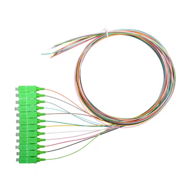
In this guide, we'll walk you through exactly how to splice fiber without a fusion splicer, covering the tools you need, the step-by-step process, performance specs, and common mistakes to avoid. By the end, you'll be equipped to make clean, low-loss connections in any. In this guide, we cover the basics of fiber optic splicing, how to perform splicing using two different methods, and finally some best practices to perform good fiber splicing. What is Fiber Optic Splicing and Why is it Needed? – #1. Use and Maintain Your. Optical fiber fast connectors, also known as cold connectors, are becoming increasingly popular due to their ease of use and quick installation. Unlike traditional fiber connectors that require epoxy and polishing, fast connectors use a mechanical splice to join the fibers. What is a. Three methods for connecting two fiber optic cables: fusion splicing, mechanical coupler, and splicing. Whether repairing a broken cable or extending a fiber run, fiber optic splicing ensures light signals travel. Fiber optic splicing is the art and science of joining two separate optical fibers to create a continuous light path. This process requires precision, patience, and a deep understanding of the delicate nature of optical fibers. Before any splicing can occur, whether it's mechanical or fusion.
[PDF]
Remove and reinstall the optical module. If the fault persists, replace the optical module with a normal one of the same type to check whether the optical module is faulty. The optical module is faulty or not securely installed. The device management or driver software has a bug. If the optical module is installed on a GE port, run the display interfaceGigabitEthernet x/x/x command to view port information when the optical module is inserted, including the rate and wavelength. Have you ever dealt with sudden network drops from faulty optical modules? Issues like this cannot only break communications, but they can really jeopardize business continuity. Understanding how to troubleshoot and prevent a failing optical module is vital for good network stability. This article. Huawei switches using non-certified optical module may not be able to read the information, can not guarantee the accuracy of the information read, recommend the use of Huawei certified optical switch module. Page 5 Changes in Issue 01 (2017-09-10) This issue is the first official release. The software version of this issue is V800R010C00. Issue () Huawei Proprietary and Confidential Copyright © Huawei Technologies Co. Page 8 40º C if a 40º C if a at 40º C if a single fan single fan single fan. The device cannot display any optical module information but services are running normally.
[PDF]

The receiver of an optical module has an overload point. Therefore, an optical attenuator is required to reduce the optical power. By introducing a precise and constant amount of optical loss, it ensures that the incoming signal remains within the optimal operating range of the receiver. A. Average optical power refers to the optical power outputted by the optical module's transmitter under normal working conditions, which can be understood as the intensity of light. The transmitted optical power is related to the proportion of "1"s in the transmitted data signal; the more "1"s, the. The receiver of an optical module has an overload point. If the optical power received by the receiver is excessively high, the optical module will be burnt. In addition, during signal transmission in a WDM system, the. 📦 For purchasing, use the RP Photonics Buyer's Guide for optical attenuators. It provides an expert-curated supplier directory, buyer-focused technical background information, and structured selection criteria to support professional procurement decisions. Optical attenuators are devices that. An optical attenuator, or fiber optic attenuator, is a device used to reduce the power level of an optical signal, either in free space or in an optical fiber. Optical internetworks are data networks composed of routers and data.
[PDF]

The LAN-WDM grid consists of four primary wavelengths in the 1310 nm window: These wavelengths were selected to minimize dispersion and allow cost-effective optical component design. LAN-WDM, short for Local Area Network Wavelength Division Multiplexing, is a specialized optical transmission technique that allows multiple high-speed optical signals to be transmitted over a single fiber using closely spaced wavelengths. Originally developed to support high-speed Ethernet. As an essential component of optical fiber communication, optical modules are optoelectronic devices that facilitate the conversion between optical and electrical signals during the transmission process. Operating at the physical layer of the OSI model, optical modules are core devices in optical. In the era of 5G, AI, and high-speed data centers, optical modules serve as the core bridge for converting electrical signals to optical signals (and vice versa), enabling fast, reliable data transmission across networks. It works by dividing light into multiple wavelengths, allowing you to send more data simultaneously over a. With the increasing demand for data centers and high-speed communications, LAN-WDM (LWDM) technology, as an emerging wavelength division multiplexing solution, is gradually becoming the focus of industry attention. This guide delves into the principles, types, applications, and future trends of WDM. Tailored for professionals sourcing solutions from CommMesh, it.
[PDF]

The optical power meter is similar to the voltohmmeter in application but measures the optical resistance (losses measured in dBm or dBM) of a cable before and after installation and provides a comparative analysis of the splices. The range of the meter is adjustable. Regularly testing fiber optic cables helps minimize network downtime, lengthens the network's longevity, reduces maintenance requirements, and helps support network reconfiguration and upgrades. These factors significantly add to the fiber optic network's long-term performance, manageability, and. Several types of tests are commonly conducted to assess and maintain the health of fiber optic networks. Continuity testing verifies that the fiber is intact and that light can pass through from one end to the other without any blockages. These test procedures assess the physical and functional qualities of fiber optic cables, connectors, and the network as a whole. Key tests include: Effective fiber testing utilizes advanced tools such as Optical. One way to test a splice is to use an Optical Power Meter. As the components like fiber, connectors, splices, LED or laser sources, detectors and receivers are being developed, testing confirms their performance specifications and helps. Regular testing of fiber optic cables is not just a preventive measure; it's an investment in the longevity and efficiency of your network. By identifying potential issues early, you can enhance.
[PDF]

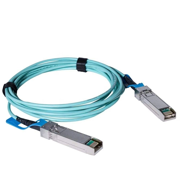
Single fiber modules (BiDi) use one fiber for both transmitting and receiving data. This saves space and money. They are easier to set up and give steady communication. They use a thin fiber. They consist of a transmitter on one end of a fiber and a receiver on the other end. Most systems operate by transmitting in one direction on one fiber and in the reverse direction on another fiber for full duplex operation. Most systems use a "transceiver" which includes both transmission and. Small Form-factor Pluggable (SFP) module is a compact, hot-swappable transceiver used for both telecommunication and data communication applications. It plugs into a network device's port, such as a switch, router, or media converter, and converts electrical signals into optical signals or vice. At the heart of fiber optic technology lies a crucial component: the optical transceiver. These modules typically consist of a transmitter, which converts electrical signals into a light signal, and a receiver, which converts the received signal back. BiDi transceiver, a compact optical transceiver with WDM (wavelength division multiplexing) technology and SFP multi-source protocol (MSA) compliance, allows fast data transmission using a single fiber optic for both sending and receiving signals, saving resources and cutting infrastructure costs.
[PDF]

No, a 10G SFP (Small Form-factor Pluggable) module is designed to operate at 10 Gigabits per second (Gbps) and is not compatible with a 1 Gigabit per second (Gb) port. Therefore, a 10G SFP module will not work. When SFP optical module is inserted into the SFP port of Gigabit switch with fiber optic patch cable or copper cable, it can realize different distance transmission. For example, the maximum transmission distance is 160 km when using SFP1G-ZXC-55 optical module and LC duplex fiber patch cable, and. 10 Gigabit Ethernet (10GE, 10GbE, or 10 GigE) is a group of computer networking technologies for transmitting Ethernet frames at a rate of 10 gigabits per second. It was first defined by the IEEE 802. For example, when using the AE-SFP-ZX160 optical module and LC duplex fiber optic patch cords, the maximum transmission. Can 1G SFP optics work with 10Gb SFP+ ports on a 10Gb switch, or vice versa? This comprehensive guide reveals the intricacies of SFP and SFP+ compatibility and provides useful solutions for network switch users. Can 1G SFP Optics Run at 10G SFP+ Port? Can 10G SFP+ Optics Run at 1G SFP Port? Can. Small form-factor pluggable or SFP Modules can be described as compact and hot-pluggable hardware that connects various networking devices such as servers, routers, and switches. Networking standards, including Ethernet, Fiber Channel, and SONET, are also used with the SFP modules, broadening their.
[PDF]

It's available for a nominal rental fee, and includes a $25 Crutchfield merchandise credit. For free personalized advice, call 1-888-291-8923. Our Advisors have listened to most of the speakers we carry, and can help you make the best choice for your system. Check each product page for other buying options. Need help? Discover high-quality optical audio splitters that let you connect multiple devices. 0, Dolby Digital, and DTS 5. 1 for immersive audio. By purchasing the products we rank, you'll get the lowest price we found while we may receive a commission at no cost to you, which will help us continue to provide you with value. Perfect for connecting HDTVs. Limited time offer, ends 05/15 Limited time offer, ends 05/10 Limited time offer, ends 05/15 Limited time offer, ends 05/18 Limited time offer, ends 05/10 Limited time offer, ends 05/10 Limited time offer, ends 05/10 Limited time offer, ends 05/10 Limited time offer, ends 05/10 Limited time offer. ➤ SPDIF AUDIO SPLITTER: The toslink digital optical adapter supports Digital 5. 1kHz, 48kHz and 96kHz. ➤ ACTIVE OPTICAL SPLITTER 1 IN 2 OUT: fiber optical audio cable splitter allows you to connect toslink audio source and split it into receiving. Uses item details. Please ensure that the connected devices have a Toslink port COMPATIBILITY - Connect any audio device Soundbar, CD/DVD.
[PDF]

They mainly consist of optoelectronic components (such as optical transmitters and receivers), functional circuits, and optical interfaces, aiming to achieve the functionalities of optical-to-electrical and electrical-to-optical signal conversion in optical fiber communication. As an essential component of optical fiber communication, optical modules are optoelectronic devices that facilitate the conversion between optical and electrical signals during the transmission process. Operating at the physical layer of the OSI model, optical modules are core devices in optical. Modern communication networks rely on optical transceivers to transfer data at the speed of light. Whether in 5G base stations, hyperscale data centers, or long-haul telecom networks, these modules convert electrical signals into optical ones — and back again — to ensure fast, stable, and. Optical modules are compact devices that convert electrical signals into optical signals and vice versa. They are used in fiber optic communication systems to transmit data over long distances with minimal loss and interference. These modules typically consist of a laser or LED transmitter, a. That is, metal medium communication represented by coaxial cables and network cables is gradually being replaced by optical fiber media.
[PDF]