In this article, you will learn the step-by-step process of testing your solar panels using a multimeter. We will cover the essential tools you need, the specific measurements to take, and how to interpret the results. A $15 multimeter and 5 minutes of testing can diagnose most solar panel problems. Measure Voc (open circuit voltage) — if it reads 0V, the panel or wiring is dead. If it reads 60–80 % of rated, a bypass diode has failed. By the end of this guide, you will be equipped with the knowledge to diagnose. Learning how to test solar panel with multimeter is useful for homeowners, technicians, farmers, and anyone using solar energy systems. A digital multimeter allows you to check voltage, current, continuity, and resistance. Fluke recommends using the Fluke 117 Electrician's Multimeter or Fluke 283 FC CAT III 1500 V Digital Multimeter to test solar modules. Here's how a technician tests solar modules with a multimeter:. A multimeter is an indispensable tool for anyone working with solar panels, allowing for accurate measurements and diagnostics. It empowers users to assess the performance, identify faults, and ensure optimal energy production. Perfect for DIY solar builders, RV owners, o. more Audio tracks for some languages.
[PDF]
Testing solar panels is easy with a multimeter! To test the current, simply connect the multimeter to the panel's output. Set it to read DC current. To test voltage, set your multimeter to. A $15 multimeter and 5 minutes of testing can diagnose most solar panel problems. Measure Voc (open circuit voltage) — if it reads 0V, the panel or wiring is dead. If it reads 60–80 % of rated, a bypass diode has failed. If Voc is normal but the system is not producing, the problem is downstream. Solar panels are usually tested under standard conditions using a light source that mimics the light from the sun on a clear day. You can use the following method if you want to test your solar panel under standard conditions. We will cover the. A multimeter is a tool that measures the voltage, current, and resistance of an electrical circuit. Fluke recommends using the Fluke 117 Electrician's Multimeter or Fluke 283 FC CAT III 1500 V Digital Multimeter to test solar modules. This helps you spot issues early and keep your system running efficiently. By the end of this guide, you will be equipped with the knowledge to diagnose.
[PDF]
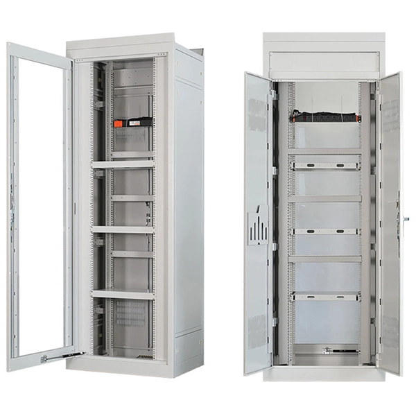
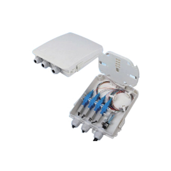
This article provides a comprehensive guide on installing fiber optic patch panels, integrating practical installation steps with insights from business intelligence and data analytics. How to Install Fiber Optic Patch Panel Only by taking the proper steps can achieve a reliable network. For your convenience, the patch panel installation guide is divided into two sections. A successful project begins with careful planning. Whether you are a seasoned professional or new to the field, this guide is designed to enhance your understanding. ⚡ Level Up Your Fiber Skills – Join the One Up Techs Skool 👉 https://www. com/oneuptechs Please like, Subscribe, and comment any questions you may have. com/oneuptechs Most techs struggle because they: ❌ Don't. Keeping this page as a placeholder for now. What are the best practices for fiber patch panel installation? The best practices below help to avoid installation issues and ensure ease of service for the system. Penetrate the enclosure from the side or bottom to minimize the risk of water intrusion. Install grommets on all openings before. The fiber optical patch panel is convenient for people to easily access the optical fiber cable in the panel box, and can protect the optical fiber cable well. In addition, the drawer type structure is also conducive to high-density wiring and good cable management. However, because the optical.
[PDF]

The process involves a combination of national infrastructure, local engineering, and property-level setup. In this guide, we'll break down the fiber installation process from start to. This guide walks you through the complete fiber installation process, from checking availability to optimizing your Wi-Fi network performance. Fiber transmits data using light signals through glass strands, delivering faster speeds and lower latency than cable or DSL connections that rely on. In this article we'll break down how fiber internet is installed - from the network fiber drop outside your house to the in-home setup with your router and gateway - and what you should expect at each stage. Fiber optic internet is generally installed in the following 5 steps, which we'll dive. Want lightning-fast internet at home? Fiber optic installation is the way to go! It's super reliable and perfect for streaming, gaming, or using multiple devices. This guide breaks down the process in easy steps so you know what to expect. BCS Consultants, a trusted fiber optic installation company based in California, provides end-to-end fiber optic services, including expert planning. However, setting up a fiber optic connection to your router can seem daunting if you're unfamiliar with the process. In this guide, we'll walk you through how to connect a fiber optic cable to a router safely and efficiently. Why Use Fiber Optic Internet? Before diving into the setup, let's quickly.
[PDF]
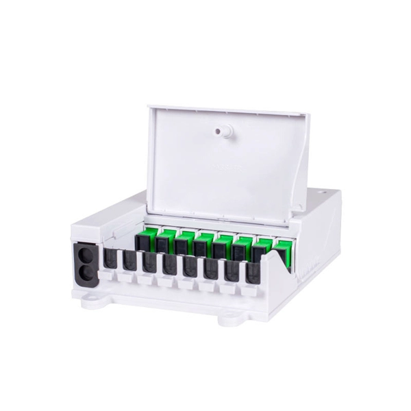
In this video, Joe would display how to connect SC fiber optical connector in 2 minutes. Related product:. Step 4 i s to affix the fiber to the connector. The fiber should be inserted into the connector until it is flush with the ferrule end. Step 5: Let the epoxy cure. These connectors ensure high-quality signal transmission, which is essential for reliable internet and communication services. SC APC connectors offer superior optical. There are many types of fiber optic connectors, including SC, LC, FC, ST, D4, MU, MT/MPO, etc. These connectors can be divided into single-mode and multi-mode fiber optic connectors according to their structure and purpose. To learn more about the types of fiber optic connectors, click here: Types. The global SC fiber optic connector market is valued at approximately 903 million USD in 2025 and is projected to grow steadily, which reflects its continuing role as a standard interface in fiber infrastructure, including plant backbones and industrial automation links, according to SC connector. SC fiber connectors, or Subscriber Connectors, are widely used in telecom and networking for their strong performance and easy handling. They're known for a secure push-pull connection that's quick to insert and remove.
[PDF]

When it comes to testing fiber optic cables, a Visual Fault Locator (VFL) is an essential tool in your toolkit. A VFL is used to detect faults, breaks, or bends in fiber optic cables by emitting a bright red light that is visible even through the fiber's jacket. Let's dive into everything you need to know about mastering VFLs. It's a cost-effective and. Visual Fault Locator (VFL) testing is one of the most fundamental inspection methods used in FTTH, ODN, and data center environments. A VFL emits a visible red laser (typically 650 nm) that travels along the fiber core and leaks out at points of excessive loss, fiber breaks, or microbends. Although. The Fiber Visual Fault Locator Kit is an essential tool for network technicians and engineers; it provides an accurate and quick method of finding such problems as breaks, bends or faults that may affect the network's operation. It works by injecting a visible red laser light (usually in the 650nm wavelength) into the fiber. When the light encounters a fault, such as a break, bend, or bad splice, it leaks out of the fiber, making the. Conducting efficient, repeatable fiber optic cable certification requires an array of specialized test equipment: Optical Loss Test Set (OLTS) – Integrates adjustable light source and power meter for efficient, Tier-1 insertion loss testing. Visual Fault Locators – Handheld devices projecting.
[PDF]
These aggregation switches typically operate at Layer 2 or Layer 3 of the OSI model, depending on the network topology and configuration requirements. The three layers of a traditional three-layer network design are the core layer, aggregation layer, and access layer. As the physical part of the aggregation layer, aggregation switches typically play a. An aggregation switch consolidates data traffic from multiple network access switches into a single high-bandwidth link directed toward a core network or data center. It is essential for larger networks requiring efficient data flow. They function as gateways to collect routing information in a point of delivery. Most medium-to-large networks follow a three-tier hierarchy: access, aggregation (sometimes called distribution), and core. Each tier has a distinct job. Access switches are the ones closest to end users and devices. They sit in wiring closets or on top of server racks, providing ports for.
[PDF]

Optical couplers can split or join signals in fibers. You can connect many users to one port with 1:n or 2:n splitters. These devices work both ways, which helps strong network communication. They help send. This small device connects or joins optical fibers together. It helps networks grow and change when needed. Learn about the two main types of fiber optic couplers: fused and planar. Fused. How to Choose the Right Fiber Coupler (FTTH, Data Center & More) Are you in the process of designing a Fiber to the Home (FTTH) network, but wondering how to split one fiber for multiple users? Or maybe you are operating a data center, and you would like to use a single signal to provide to. Fiber optic couplers are optical devices that connect three or more fiber ends, dividing one input between two or more outputs, or combining two or more inputs into one output. The device allows the transmission of light waves through multiple paths. Fiber optic couplers can either be passive or. A fiber optic coupler is a passive optical component that splits, combines, taps, or redistributes light between optical fibers. In real-world networks, couplers let one signal reach many users, allow several signals to share one fiber path, or sample a small amount of light for monitoring. 5/125 µm fiber, with low insertion loss and a broad operating wavelength range from 800 to 1600 nm. The 1x2 and 2x2.
[PDF]
Long Expansion Cycle: Optical fiber preform production has high technological barriers, and the expansion cycle can take as long as 18-24 months. Even if manufacturers start expanding immediately, the new capacity will not be available until at least 2027. This phenomenon is the result of multiple factors, including tight supply of optical fiber preforms (preforms), long expansion cycles for optical fiber production capacity, and the explosive growth of emerging applications such as AI computing power and drones. The expansion cycle of optical fibers is generally less than 6 months, and fiber optic cables can take 3 months. The expansion of production requires the purchase of equipment and the construction of factories. At the heart of this transformation lies fiber optic cable manufacturing, a precise and sophisticated process that powers our interconnected world. With the global fiber optic market reaching $6 billion and growing at 10% annually, the need for high-quality manufacturing solutions has never been. The manufacturing process of fiber optic cables involves several intricate steps that culminate in the production of high-performance data transmission solutions. This process begins with the creation of a preform, which serves as the foundation for the optical fibers within the cable. This intricate process combines cutting-edge technology, precise engineering, and.
[PDF]
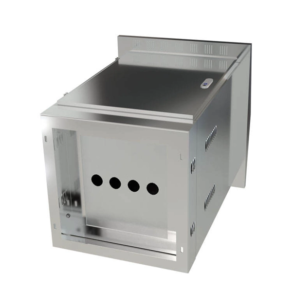
This video shows real on-site footage of electrical installation, demonstrating safe and standardized wiring methods used by professionals. more Learn how to wire a distribution box step by step!. A distribution box is the heart of any electrical system. It takes the incoming power and safely distributes it to different circuits throughout your building. Whether in a home or an industrial facility, this box keeps your electrical setup organized, functional, and efficient. However, the key to. In modern electrical systems, cable distribution boxes (also known as electrical distribution boxes or distribution boxes) play a crucial role as the key hub for managing, distributing, and protecting circuits. It serves as a central hub for distributing electricity throughout a building, ensuring that power is delivered safely and efficiently to all the required locations. Box installation: Make sure that Distribution box has been correctly installed and fixed. Material preparation: Prepare the required circuit breakers, wires, wiring ties and other materials, and ensure that they meet the design drawings and installation requirements. Location determination:.
[PDF]

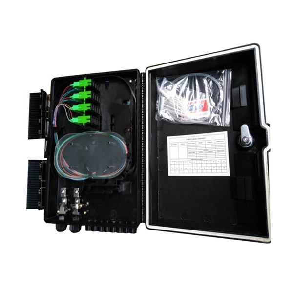
In this step-by-step tutorial, learn how to splice fiber optic cables like a pro — perfect for telecom technicians, network engineers, and field techs. more 🔧 Watch a real-time fiber optic splicing demo in action!. Fiber cable splicing is a critical step in building reliable fiber optic networks. Whether in data centers, telecom rooms, or outdoor FTTx deployments, proper splicing inside a fiber enclosure ensures low signal loss, long-term stability, and easy maintenance. This guide explains what fiber cable. In this guide, we cover the basics of fiber optic splicing, how to perform splicing using two different methods, and finally some best practices to perform good fiber splicing. What is Fiber Optic Splicing and Why is it Needed? – #1. Whether repairing a broken cable or extending a fiber run, fiber optic splicing ensures light signals travel. Regardless of your level of experience, creating high-quality, high-performance fiber optic networks requires developing your skills in fusion splicing. This guide reveals the secrets to fusion splicing with little fluff—just proven, straightforward techniques refined from years of work in the.
[PDF]

The optical power meter is similar to the voltohmmeter in application but measures the optical resistance (losses measured in dBm or dBM) of a cable before and after installation and provides a comparative analysis of the splices. The range of the meter is adjustable. Regularly testing fiber optic cables helps minimize network downtime, lengthens the network's longevity, reduces maintenance requirements, and helps support network reconfiguration and upgrades. These factors significantly add to the fiber optic network's long-term performance, manageability, and. Several types of tests are commonly conducted to assess and maintain the health of fiber optic networks. Continuity testing verifies that the fiber is intact and that light can pass through from one end to the other without any blockages. These test procedures assess the physical and functional qualities of fiber optic cables, connectors, and the network as a whole. Key tests include: Effective fiber testing utilizes advanced tools such as Optical. One way to test a splice is to use an Optical Power Meter. As the components like fiber, connectors, splices, LED or laser sources, detectors and receivers are being developed, testing confirms their performance specifications and helps. Regular testing of fiber optic cables is not just a preventive measure; it's an investment in the longevity and efficiency of your network. By identifying potential issues early, you can enhance.
[PDF]

This wikiHow article will teach you how to splice a cut fiber optic cable back together with a fiber optic stripper and cutter and a fiber optic crimper. Trim off any frayed or damaged ends of the cable. While a cut or damaged fiber optic cable can temporarily take your network down, it is possible to quickly fix the cable with the right tools. When fiber cables sustain damage, specialized repair techniques help restore connectivity and maintain data integrity. This comprehensive guide outlines professional fiber optic repair protocols that align with industry best practices. Adhering to precise methodologies, we can mend impaired cables. Get your fiber optic cable repair tools together. You'll need strippers, cleavers, splice trays, a splicing machine, and cleaning materials like alcohol wipes. Leave some extra cable before the damage point. It makes cutting and splicing easier. However, you don't need to panic! It can still be fixed. If you have the right tools and knowledge, you can definitely find the solution. Understanding the causes and types of fiber optic cable damage helps detect. Whether you're a network technician, IT professional, or telecom operator, you'll find practical steps, tools, and tips to restore connectivity with minimal loss. Dekam Fiber's state-of-the-art solutions, including our UltraRepair kits, make these processes accessible and reliable.
[PDF]