
In this article, you will learn the step-by-step process of testing your solar panels using a multimeter. We will cover the essential tools you need, the specific measurements to take, and how to interpret the results. A $15 multimeter and 5 minutes of testing can diagnose most solar panel problems. Measure Voc (open circuit voltage) — if it reads 0V, the panel or wiring is dead. If it reads 60–80 % of rated, a bypass diode has failed. By the end of this guide, you will be equipped with the knowledge to diagnose. Learning how to test solar panel with multimeter is useful for homeowners, technicians, farmers, and anyone using solar energy systems. A digital multimeter allows you to check voltage, current, continuity, and resistance. Fluke recommends using the Fluke 117 Electrician's Multimeter or Fluke 283 FC CAT III 1500 V Digital Multimeter to test solar modules. Here's how a technician tests solar modules with a multimeter:. A multimeter is an indispensable tool for anyone working with solar panels, allowing for accurate measurements and diagnostics. It empowers users to assess the performance, identify faults, and ensure optimal energy production. Perfect for DIY solar builders, RV owners, o. more Audio tracks for some languages.
[PDF]
Testing solar panels is easy with a multimeter! To test the current, simply connect the multimeter to the panel's output. Set it to read DC current. To test voltage, set your multimeter to. A $15 multimeter and 5 minutes of testing can diagnose most solar panel problems. Measure Voc (open circuit voltage) — if it reads 0V, the panel or wiring is dead. If it reads 60–80 % of rated, a bypass diode has failed. If Voc is normal but the system is not producing, the problem is downstream. Solar panels are usually tested under standard conditions using a light source that mimics the light from the sun on a clear day. You can use the following method if you want to test your solar panel under standard conditions. We will cover the. A multimeter is a tool that measures the voltage, current, and resistance of an electrical circuit. Fluke recommends using the Fluke 117 Electrician's Multimeter or Fluke 283 FC CAT III 1500 V Digital Multimeter to test solar modules. This helps you spot issues early and keep your system running efficiently. By the end of this guide, you will be equipped with the knowledge to diagnose.
[PDF]

The process involves a combination of national infrastructure, local engineering, and property-level setup. In this guide, we'll break down the fiber installation process from start to. This guide walks you through the complete fiber installation process, from checking availability to optimizing your Wi-Fi network performance. Fiber transmits data using light signals through glass strands, delivering faster speeds and lower latency than cable or DSL connections that rely on. In this article we'll break down how fiber internet is installed - from the network fiber drop outside your house to the in-home setup with your router and gateway - and what you should expect at each stage. Fiber optic internet is generally installed in the following 5 steps, which we'll dive. Want lightning-fast internet at home? Fiber optic installation is the way to go! It's super reliable and perfect for streaming, gaming, or using multiple devices. This guide breaks down the process in easy steps so you know what to expect. BCS Consultants, a trusted fiber optic installation company based in California, provides end-to-end fiber optic services, including expert planning. However, setting up a fiber optic connection to your router can seem daunting if you're unfamiliar with the process. In this guide, we'll walk you through how to connect a fiber optic cable to a router safely and efficiently. Why Use Fiber Optic Internet? Before diving into the setup, let's quickly.
[PDF]
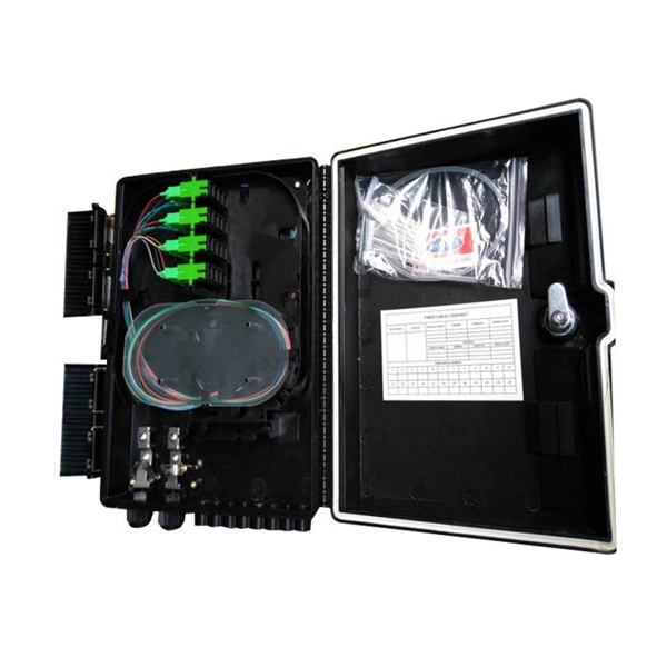
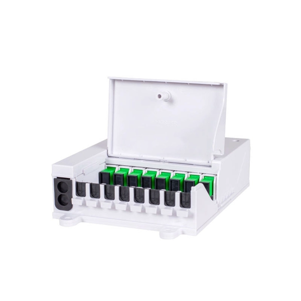
This article provides a comprehensive guide on installing fiber optic patch panels, integrating practical installation steps with insights from business intelligence and data analytics. How to Install Fiber Optic Patch Panel Only by taking the proper steps can achieve a reliable network. For your convenience, the patch panel installation guide is divided into two sections. A successful project begins with careful planning. Whether you are a seasoned professional or new to the field, this guide is designed to enhance your understanding. ⚡ Level Up Your Fiber Skills – Join the One Up Techs Skool 👉 https://www. com/oneuptechs Please like, Subscribe, and comment any questions you may have. com/oneuptechs Most techs struggle because they: ❌ Don't. Keeping this page as a placeholder for now. What are the best practices for fiber patch panel installation? The best practices below help to avoid installation issues and ensure ease of service for the system. Penetrate the enclosure from the side or bottom to minimize the risk of water intrusion. Install grommets on all openings before. The fiber optical patch panel is convenient for people to easily access the optical fiber cable in the panel box, and can protect the optical fiber cable well. In addition, the drawer type structure is also conducive to high-density wiring and good cable management. However, because the optical.
[PDF]
In this video, Joe would display how to connect SC fiber optical connector in 2 minutes. Related product:. Step 4 i s to affix the fiber to the connector. The fiber should be inserted into the connector until it is flush with the ferrule end. Step 5: Let the epoxy cure. These connectors ensure high-quality signal transmission, which is essential for reliable internet and communication services. SC APC connectors offer superior optical. There are many types of fiber optic connectors, including SC, LC, FC, ST, D4, MU, MT/MPO, etc. These connectors can be divided into single-mode and multi-mode fiber optic connectors according to their structure and purpose. To learn more about the types of fiber optic connectors, click here: Types. The global SC fiber optic connector market is valued at approximately 903 million USD in 2025 and is projected to grow steadily, which reflects its continuing role as a standard interface in fiber infrastructure, including plant backbones and industrial automation links, according to SC connector. SC fiber connectors, or Subscriber Connectors, are widely used in telecom and networking for their strong performance and easy handling. They're known for a secure push-pull connection that's quick to insert and remove.
[PDF]

The optical power meter is similar to the voltohmmeter in application but measures the optical resistance (losses measured in dBm or dBM) of a cable before and after installation and provides a comparative analysis of the splices. The range of the meter is adjustable. Regularly testing fiber optic cables helps minimize network downtime, lengthens the network's longevity, reduces maintenance requirements, and helps support network reconfiguration and upgrades. These factors significantly add to the fiber optic network's long-term performance, manageability, and. Several types of tests are commonly conducted to assess and maintain the health of fiber optic networks. Continuity testing verifies that the fiber is intact and that light can pass through from one end to the other without any blockages. These test procedures assess the physical and functional qualities of fiber optic cables, connectors, and the network as a whole. Key tests include: Effective fiber testing utilizes advanced tools such as Optical. One way to test a splice is to use an Optical Power Meter. As the components like fiber, connectors, splices, LED or laser sources, detectors and receivers are being developed, testing confirms their performance specifications and helps. Regular testing of fiber optic cables is not just a preventive measure; it's an investment in the longevity and efficiency of your network. By identifying potential issues early, you can enhance.
[PDF]

Start by separating your Ethernet cable into two separate cables and connecting them to the back of the Ethernet cable splitter. Once the cables are securely connected, connect the other ends to your desired devices. Ensure that the cables are tightly secure and that all connections. When you need to connect multiple wired devices like computers, printers, and IP phones, but only have one Ethernet wall port, using an Ethernet splitter or network switch can expand your connectivity without rewiring. This guide explains your options and helps you choose the best solution for your. An Ethernet splitter is a small device that allows two Ethernet-connected devices to share a single cable run. It does not increase speed or create extra bandwidth. It simply divides signal pairs. This tool works best in basic setups where running another cable is not possible. An Ethernet splitter. Ethernet cable splitter wiring diagrams are essential for anyone who needs to connect multiple devices in a home or office network. With the ever-increasing popularity of high-speed internet and streaming services, providing reliable connections to multiple devices is becoming increasingly. An Ethernet splitter doesn't actually split a single Ethernet connection to provide separate internet access to two devices. Instead, it utilizes only two of the four pairs of wires within a single Ethernet cable to connect two devices, requiring two splitters for the setup to function correctly.
[PDF]

This wikiHow article will teach you how to splice a cut fiber optic cable back together with a fiber optic stripper and cutter and a fiber optic crimper. Trim off any frayed or damaged ends of the cable. While a cut or damaged fiber optic cable can temporarily take your network down, it is possible to quickly fix the cable with the right tools. When fiber cables sustain damage, specialized repair techniques help restore connectivity and maintain data integrity. This comprehensive guide outlines professional fiber optic repair protocols that align with industry best practices. Adhering to precise methodologies, we can mend impaired cables. Get your fiber optic cable repair tools together. You'll need strippers, cleavers, splice trays, a splicing machine, and cleaning materials like alcohol wipes. Leave some extra cable before the damage point. It makes cutting and splicing easier. However, you don't need to panic! It can still be fixed. If you have the right tools and knowledge, you can definitely find the solution. Understanding the causes and types of fiber optic cable damage helps detect. Whether you're a network technician, IT professional, or telecom operator, you'll find practical steps, tools, and tips to restore connectivity with minimal loss. Dekam Fiber's state-of-the-art solutions, including our UltraRepair kits, make these processes accessible and reliable.
[PDF]

A 630A MCCB means the breaker is rated to handle up to 630 amperes of continuous current without tripping under normal conditions. This type of MCCB is commonly used in industrial power distribution panels, commercial buildings, and large electrical systems where higher current. A Molded Case Circuit Breaker (MCCB) is a protective device designed to automatically disconnect electrical circuits during overloads or short circuits. This type of. This ComPacT NSX630N is a complete 3P 3d fixed circuit breaker designed to optimize space and breaking capacity. It is an optimal choice for all standard and specific applications. The breaking capacity (Icu) is 50kA rms at 415VAC 50/60Hz. This product. Fuji Molded Case Circuit Breakers are more compact (especially 100A, 125A, 250A frames) than any breakers on the market, so they take up less space in control panels. U denotes non-interchangeable trip unit. With a 630A frame rating and adjustable settings from 400A to 630A, it offers flexible protection for high-power applications. Ir = 300 - 630A; Icu = Ics = 65kA at AC 440V How to request a quotation How can I request a quotation for more than one product? (Watchlist). GENLITEC POWER® GTS630 630A Automatic Transfer Switch (ATS) Panel is designed for seamless and automatic power switching between the main utility supply and backup generators. Engineered for high-power applications, this ATS ensures uninterrupted power supply, reducing downtime and enhancing.
[PDF]

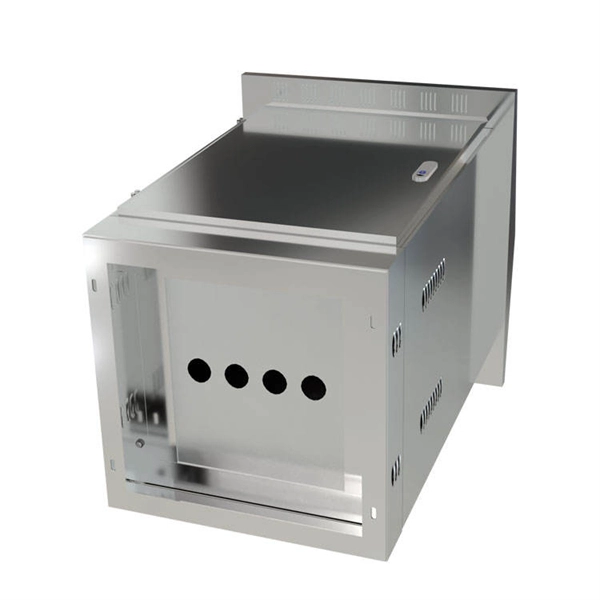
Cable tray pricing depends on materials, coatings, size, supplier margins, and order quantity —plus hidden costs like shipping and installation. This guide breaks down everything buyers need to know, from price trends to cost-saving tips. Understanding the cable tray installation cost per meter is essential for effective budget planning. Costs vary based on tray material (steel, aluminum, or fiberglass), size, design (ladder or solid bottom), and installation complexity. The average cable tray price per meter ranges from $2 to. Ask ten buyers about cable tray cost, and most of them will point to the rate per meter. That number matters, but it's rarely the one that decides whether a project stays within budget. The real cost shows up later, during installation, during upgrades, and during the first few years of operation. The selection of the method of carrying wires is based on two points: the cost of the components and the cost of work. Although metal pipes (conduit) may appear cheap initially, they tend to be the most costly option when the job is finally complete, since they consume a lot of time to install. Cable tray pricing represents a crucial consideration in modern electrical infrastructure projects, encompassing various factors that influence the overall cost-effectiveness of cable management systems. The price structure typically reflects the material composition, whether aluminum, steel, or.
[PDF]
Connecting a fiber optic cable to a router might seem daunting at first, but with the right tools and a bit of patience, it's a straightforward process. Here's a step-by-step guide to help you through it. Understand the Basics Before diving in, familiarize yourself with. However, setting up a fiber optic connection to your router can seem daunting if you're unfamiliar with the process. In this guide, we'll walk you through how to connect a fiber optic cable to a router safely and efficiently. Our Experts are helping user's, who are facing issues with their tech gadgets like Router, Modem and extender. If you. The process to connect fiber optic cable to router requires careful attention to detail, but I'll walk you through every critical step with the precision and clarity you deserve. This comprehensive guide combines industry standards with field-tested practices to ensure you achieve a rock-solid. Setting up a fiber internet connection requires understanding key hardware components and following a specific connection sequence to establish your home network. Check compatibility: Before you begin, make sure your router supports fiber optic connection.
[PDF]
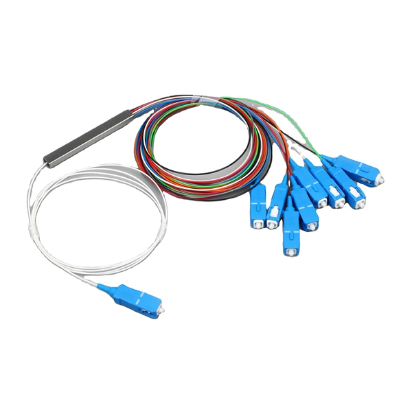
Beam splitters are classified by construction (plate, cube, pellicle, polka dot) and by function (standard, non-polarizing, polarizing, dichroic). Construction determines ghosting, damage threshold, and form factor. Function determines how polarization and wavelength are. Plate beamsplitter s Plate beamsplitters consist of a thin plate of optical crown glass with a different type of coating deposited on each side. The first surface is coated with an all-dielectric film having partial reflection properties over either the visible or the near-infrared spectrum. The. A beam splitter divides incident light into reflected and transmitted beams at a specified R/T ratio. For a lossless beam splitter, R + T = 1. When comparing beam splitters, always check whether the specified R/T ratio is for unpolarized light or for a specific polarization. The numbers can differ.
[PDF]
In this guide, we'll break down the key wiring layout, main control panel components, and how everything connects — from the main power isolator to the PLC and sensors on the production line. Every roll forming machine relies on a precisely designed electrical control and wiring system. This system ensures that motors, sensors, drives, and. This guide will walk through the key points you need to consider when preparing electrical schematics and wiring diagrams for a roll forming machine. This guide breaks down the entire electrical system of a modern roll forming machine — from incoming 3-phase supply to flying shear synchronization — with: A complete roll forming electrical system contains: Roll forming machines are typically built for: Voltage mismatch damages VFDs, transformers. Electrical design is the backbone of any roll forming line. Electrical design is the backbone of any roll forming line. These machines convert metal coil.
[PDF]

