
In this article, you will learn the step-by-step process of testing your solar panels using a multimeter. We will cover the essential tools you need, the specific measurements to take, and how to interpret the results. A $15 multimeter and 5 minutes of testing can diagnose most solar panel problems. Measure Voc (open circuit voltage) — if it reads 0V, the panel or wiring is dead. If it reads 60–80 % of rated, a bypass diode has failed. By the end of this guide, you will be equipped with the knowledge to diagnose. Learning how to test solar panel with multimeter is useful for homeowners, technicians, farmers, and anyone using solar energy systems. A digital multimeter allows you to check voltage, current, continuity, and resistance. Fluke recommends using the Fluke 117 Electrician's Multimeter or Fluke 283 FC CAT III 1500 V Digital Multimeter to test solar modules. Here's how a technician tests solar modules with a multimeter:. A multimeter is an indispensable tool for anyone working with solar panels, allowing for accurate measurements and diagnostics. It empowers users to assess the performance, identify faults, and ensure optimal energy production. Perfect for DIY solar builders, RV owners, o. more Audio tracks for some languages.
[PDF]
Testing solar panels is easy with a multimeter! To test the current, simply connect the multimeter to the panel's output. Set it to read DC current. To test voltage, set your multimeter to. A $15 multimeter and 5 minutes of testing can diagnose most solar panel problems. Measure Voc (open circuit voltage) — if it reads 0V, the panel or wiring is dead. If it reads 60–80 % of rated, a bypass diode has failed. If Voc is normal but the system is not producing, the problem is downstream. Solar panels are usually tested under standard conditions using a light source that mimics the light from the sun on a clear day. You can use the following method if you want to test your solar panel under standard conditions. We will cover the. A multimeter is a tool that measures the voltage, current, and resistance of an electrical circuit. Fluke recommends using the Fluke 117 Electrician's Multimeter or Fluke 283 FC CAT III 1500 V Digital Multimeter to test solar modules. This helps you spot issues early and keep your system running efficiently. By the end of this guide, you will be equipped with the knowledge to diagnose.
[PDF]
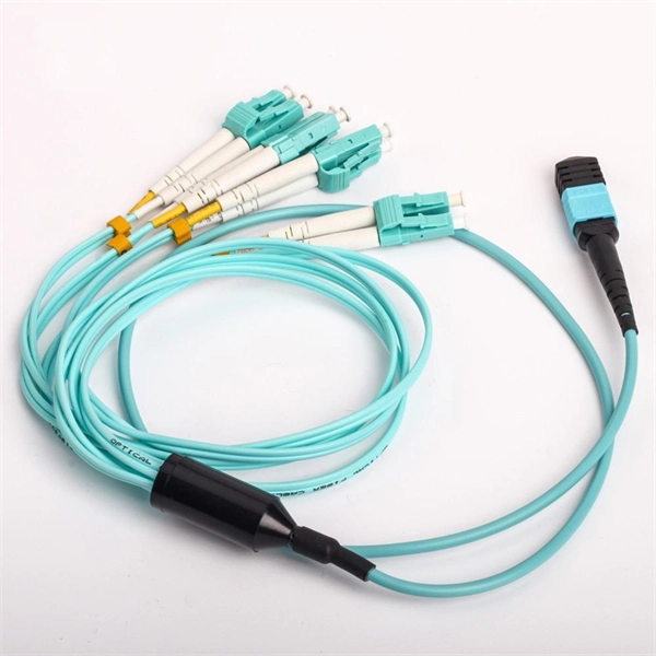
In this video, Joe would display how to connect SC fiber optical connector in 2 minutes. Related product:. Step 4 i s to affix the fiber to the connector. The fiber should be inserted into the connector until it is flush with the ferrule end. Step 5: Let the epoxy cure. These connectors ensure high-quality signal transmission, which is essential for reliable internet and communication services. SC APC connectors offer superior optical. There are many types of fiber optic connectors, including SC, LC, FC, ST, D4, MU, MT/MPO, etc. These connectors can be divided into single-mode and multi-mode fiber optic connectors according to their structure and purpose. To learn more about the types of fiber optic connectors, click here: Types. The global SC fiber optic connector market is valued at approximately 903 million USD in 2025 and is projected to grow steadily, which reflects its continuing role as a standard interface in fiber infrastructure, including plant backbones and industrial automation links, according to SC connector. SC fiber connectors, or Subscriber Connectors, are widely used in telecom and networking for their strong performance and easy handling. They're known for a secure push-pull connection that's quick to insert and remove.
[PDF]

The process involves a combination of national infrastructure, local engineering, and property-level setup. In this guide, we'll break down the fiber installation process from start to. This guide walks you through the complete fiber installation process, from checking availability to optimizing your Wi-Fi network performance. Fiber transmits data using light signals through glass strands, delivering faster speeds and lower latency than cable or DSL connections that rely on. In this article we'll break down how fiber internet is installed - from the network fiber drop outside your house to the in-home setup with your router and gateway - and what you should expect at each stage. Fiber optic internet is generally installed in the following 5 steps, which we'll dive. Want lightning-fast internet at home? Fiber optic installation is the way to go! It's super reliable and perfect for streaming, gaming, or using multiple devices. This guide breaks down the process in easy steps so you know what to expect. BCS Consultants, a trusted fiber optic installation company based in California, provides end-to-end fiber optic services, including expert planning. However, setting up a fiber optic connection to your router can seem daunting if you're unfamiliar with the process. In this guide, we'll walk you through how to connect a fiber optic cable to a router safely and efficiently. Why Use Fiber Optic Internet? Before diving into the setup, let's quickly.
[PDF]
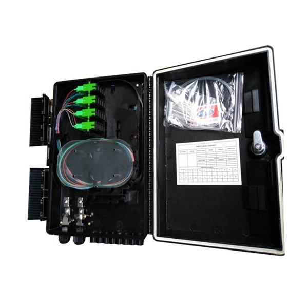
This article provides a comprehensive guide on installing fiber optic patch panels, integrating practical installation steps with insights from business intelligence and data analytics. How to Install Fiber Optic Patch Panel Only by taking the proper steps can achieve a reliable network. For your convenience, the patch panel installation guide is divided into two sections. A successful project begins with careful planning. Whether you are a seasoned professional or new to the field, this guide is designed to enhance your understanding. ⚡ Level Up Your Fiber Skills – Join the One Up Techs Skool 👉 https://www. com/oneuptechs Please like, Subscribe, and comment any questions you may have. com/oneuptechs Most techs struggle because they: ❌ Don't. Keeping this page as a placeholder for now. What are the best practices for fiber patch panel installation? The best practices below help to avoid installation issues and ensure ease of service for the system. Penetrate the enclosure from the side or bottom to minimize the risk of water intrusion. Install grommets on all openings before. The fiber optical patch panel is convenient for people to easily access the optical fiber cable in the panel box, and can protect the optical fiber cable well. In addition, the drawer type structure is also conducive to high-density wiring and good cable management. However, because the optical.
[PDF]
This guide walks you through the complete fiber installation process, from checking availability to optimizing your Wi-Fi network performance. Upgrading to fibre internet involves replacing your existing copper cables with new fibre-optic ones. This upgrade brings faster speeds and more reliable connectivity. Here is what the installation process is like: One of our technicians will visit your home, remove the old copper wiring and. If you need Fiber Optic Cable Installation in Malta or areas close by allow us to assist you by connecting you with specialized pros who can do the work you request. Step 1: Planning Before any installation begins, thorough planning is essential. This includes determining the network's requirements, such as bandwidth, distance, and the number of. This guide will explain the entire set of activities involved in installing Fiber optic cable contractors -from the early planning stage right through testing-for facility managers, IT teams, and low-voltage contractors to build high-performance networks safely and efficiently. The processes. The Fiber Optic Association, Inc. (FOA) was founded in 1995 to help develop the workforce to build the fiber optic networks to support a rapid expansion in communications and the Internet. The charter of the FOA was to promote professionalism in fiber optics through education, certification, and. We offer :- For more information email us on sales@merlin.
[PDF]

A 630A MCCB means the breaker is rated to handle up to 630 amperes of continuous current without tripping under normal conditions. This type of MCCB is commonly used in industrial power distribution panels, commercial buildings, and large electrical systems where higher current. A Molded Case Circuit Breaker (MCCB) is a protective device designed to automatically disconnect electrical circuits during overloads or short circuits. This type of. This ComPacT NSX630N is a complete 3P 3d fixed circuit breaker designed to optimize space and breaking capacity. It is an optimal choice for all standard and specific applications. The breaking capacity (Icu) is 50kA rms at 415VAC 50/60Hz. This product. Fuji Molded Case Circuit Breakers are more compact (especially 100A, 125A, 250A frames) than any breakers on the market, so they take up less space in control panels. U denotes non-interchangeable trip unit. With a 630A frame rating and adjustable settings from 400A to 630A, it offers flexible protection for high-power applications. Ir = 300 - 630A; Icu = Ics = 65kA at AC 440V How to request a quotation How can I request a quotation for more than one product? (Watchlist). GENLITEC POWER® GTS630 630A Automatic Transfer Switch (ATS) Panel is designed for seamless and automatic power switching between the main utility supply and backup generators. Engineered for high-power applications, this ATS ensures uninterrupted power supply, reducing downtime and enhancing.
[PDF]

A simple 1-core FTTH drop cable costs around $0. 13 per foot, while a 288-count optical fiber cable for building backbones can reach $6 per foot or more. In this article, we'll take a closer look at the main parameters determining the price of a fiber patch cord, provide up-to-date pricing ranges, and assist you in becoming a smarter buyer—regardless of whether you are making a purchasing decision for a project, replenishing inventory, or placing an. Check each product page for other buying options. Need help?. Fiber-optic cable materials typically cost $1 to $6 per linear foot, depending on fiber count and cable type. Commercial building installations with 100-200 network drops generally range from $15,000 to $30,000. Single-mode fiber costs less per foot than multimode fiber, but it requires more. Knowing how much fiber optic cable costs, which factors can impact cost, and key cost considerations can help you avoid unnecessary expense and get the most out of your budget. First. Get low-loss fiber patch cables & cords with various connector options that support fiber optic cabling up to 400G. Customized cables available. Main cost drivers include cable grade (indoor vs outdoor, armoured), distance, and labor for trenching, splicing, and termination. This guide presents ranges in USD and practical price estimates to help.
[PDF]

In this video, we'll walk you through the process of wiring a home distribution box with a detailed connection diagram. Whether you're an electrician or a DIY enthusiast, this guide will help you understand the basics of home electrical distribution. more Welcome to our channel! In this video. A distribution box is the heart of any electrical system. It takes the incoming power and safely distributes it to different circuits throughout your building. However, the key to. Material preparation: Prepare the required circuit breakers, wires, wiring ties and other materials, and ensure that they meet the design drawings and installation requirements. Location determination: Determine the installation position of the circuit breaker according to the position of the. In modern electrical systems, cable distribution boxes (also known as electrical distribution boxes or distribution boxes) play a crucial role as the key hub for managing, distributing, and protecting circuits. Whether it is residential buildings, commercial facilities or industrial sites, the. Hey, in this article we are going to see the Single Phase Distribution Box Wiring Diagram and Connection Procedure. A distribution board or distribution box is where the main power supply is distributed to multiple loads.
[PDF]

These numerical codes, ranging from 1 to 99, uniquely identify the functions of protective relays, associated devices, and control equipment in electrical power systems. In electric power systems and industrial automation, ANSI Device Numbers can be used to identify equipment and devices in a system such as relays, circuit breakers, or instruments. The device numbers are enumerated in ANSI / IEEE Standard C37. 2 Standard for Electrical Power System Device Function. According to the ANSI/IEEE standards, device function numbers are crucial identifiers in power system protection and control engineering. ANSI IEEE Standard Device Numbers are below: (the more commonly used ones are in bold) 86T is a Lockout Relay for a. The widely used United Sates standard ANSI/IEEE C37. Even in those parts of the world where IEC standards are predominate, the use of ANSI numbering. For power grid systems, ANSI and IEEE functional number codes dictate the use and restrictions of both the devices themselves, as well as the functions of those devices within the scope of a circuit. These devices include switches, disconnects, circuit breakers, generators, and motors. Instead of verbal descriptions, we use numbers to describe the functions of a relay. Why use numbers instead of words? Efficiency.
[PDF]
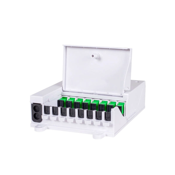
We manufacture and stock Distributions Boxes in various sizes from 3 outlets to 14 outlets:. We manufacture and stock Distributions Boxes in various sizes from 3 outlets to 14 outlets:. BOX WALL FS NEMA RATE SC APC 24 PORT Outdoor Wall Box FieldSmart Wall Mount Outdoor Rated (24 port capacity) panel panel, 24 Singlemode SC/APC Ports, loaded with tight buffer singlemode pigtail in Clearview patch and splice tight buffer singlemode pigtail in Clearview patch and splice Cassette. Jensen's wastewater distribution boxes offer a comprehensive range of reliable solutions for efficient wastewater distribution in septic systems. Today, electrical systems are essential for homes and industries. But what exactly is a power distribution box, and why is it so essential in our daily lives? The DB panel board controls the flow of electricity. This increases stopping power and steering responsiveness, decreases trailer sway, and improves overall stability. This is particularly useful when towing heavy loads like RVs, which can otherwise cause the tow vehicle to become.
[PDF]

This guide shows you how to organize circuit breaker wiring properly. You will learn to build a safe, efficient, and professional electrical system today. Circuit breaker wiring configurations involve organizing main switches, busbars, and branch breakers within a distribution box. While some homeowners may attempt this, it's highly recommended to hire a qualified, licensed electrician for circuit breaker box wiring. This is a complex and potentially dangerous task that involves working with high voltage electricity. Mistakes can lead to serious injury, fire, or damage to. A breaker box, also known as a circuit breaker panel, is an essential component of any electrical system. It is responsible for distributing electricity throughout a building, ensuring that each circuit receives the proper amount of power. To understand how a breaker box works, it is helpful to. When installing or troubleshooting a power distribution system, understanding how to correctly connect the main electrical supply to the control panel is crucial. The first step involves running a dedicated cable from the incoming supply to the distribution panel, ensuring it is rated for the load. How to read these diagrams. This page contains wiring diagrams for a service panel breaker box and circuit breakers including: 15amp, 20amp, 30amp, and 50amp as well as a GFCI breaker and an isolated ground circuit. Messy distribution boxes are dangerous and very hard to fix.
[PDF]

Connect the phase and neutral wires from the input power supply to the input of the Main MCB. They can correct voltage, but they have no effect on power factor. They are installed in series between the Source and Load. They are a voltage source, they add or subtract. When you're towing something much heavier or lighter than usual, you'll need to make adjustments to your weight-distribution hitch. Fortunately, adjusting a weight-distribution hitch for safe towing is fairly straightforward. But if you need more guidance on how to connect your hitch in the first. This green leaf icon designates information specifically for Vista® Green Underground Distribution Switchgear that uses a CO mix insulating gas. Unless otherwise designated, instructions provided apply to all manual 2 Vista switchgear products. Take the appropriate rating of MCB and RCCB as per your load requirements. Identify the Input and Output sides of the MCBs and RCCBs. If you use. Use the Exchange admin center (EAC) or Exchange Online PowerShell to create, modify, or remove distribution lists in your Exchange Online organization. Exchange Online supports four types of groups that can be used to distribute messages: Distributions lists that can be used only to distribute. This bulletin contains instructions for installing Square D brand I-Line circuit breaker power distribution panelboards.
[PDF]