
The basic design of an optocoupler consists of a light source, usually an LED (Light-Emitting Diode), driven by the input signal which could be a digital or analogue voltage/current depending upon the characteristics of the light source. An optocoupler (or opto-isolator) is a component that transfer signals between circuits using light. In this guide, you'll learn how they work and how you can use one in your own projects. Optocouplers are very useful when you need to isolate different sections of a circuit, for example in power. Optocouplers, also known as opto-isolators, uses infrared light to transfer electrical signals between two electrically isolated circuits and are commonly classified by their photosensitive output device What is an Optocoupler? An optocoupler (also called an opto-isolator, photo-coupler, or optical. An optocoupler is a tiny part that moves signals between circuits without letting electricity jump across. It uses light to do the job, which helps keep things safe. That way, noisy signals, voltage spikes, or weird grounding issues don't mess with sensitive electronics. Opto-isolators prevent high voltages from affecting the system receiving the signal. We will explore the basics of optocoupler selection and their functionality, helping.
[PDF]
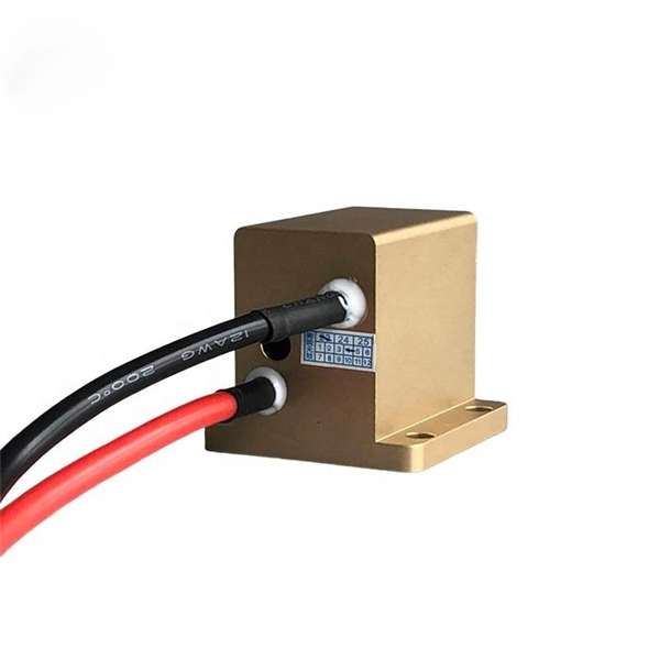
Founded in 1984, Zhejiang Dongya Electronic Co., Ltd specialize in designing, manufacturing and selling high and low-voltage DC contactors, relays, shunts, hydraulic circuit breakers, BDUs and other products. DONGYA is industrial technology Professional design and manufacture dc contactors manufacturers. was established in 1984, with registered capital of USD 1,482,353. We offer dozens of product series and more than 300 models with annual production capacity. Zhejiang Dongya Electronics Co. We have set up.
[PDF]
Learn how to splice 4-fiber optic cables using ODF in this complete step-by-step tutorial. Whether you are a beginner or a professional in fiber optic networking, this guide will help you splice fiber cables accurately, manage connections with ODF panels, and ensure. This complete guide explores everything you need to know about ODFs — from their structure, types, and key components, to installation best practices and modern design trends. Whether you're building a central office, data center, or FTTx distribution network, understanding the right ODF. How to Splice 4-Fiber Optic Cable with ODF | Step-by-Step Fiber Optic Splicing Tutorial. This guide demystifies ODF, exploring their design, core functions, types, and how they. An Optical Distribution Frame (ODF) is the central hub for fiber splicing, termination, patching, and cable protection in modern optical networks. It's where incoming and outgoing cables meet. It does four key things: Think of it as the central hub for your fiber network. Without it, cables get tangled. This article explores the types, components, applications, installation, and maintenance best practices, providing a.
[PDF]
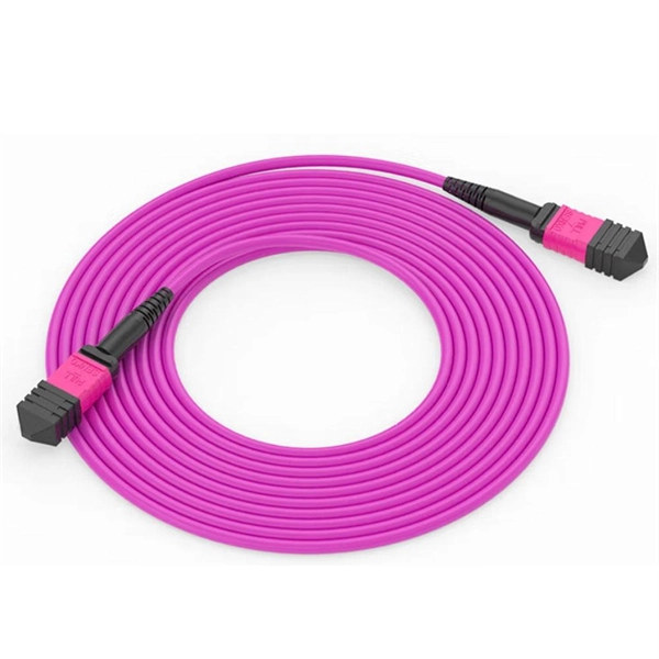
It plugs into network equipment (like switches, routers, or servers) and its primary function is to convert electrical signals from the device into light signals for transmission over fiber optic cables, and then convert received light signals back into electrical signals. People can also refer to an optical transceiver as a fibre optic transceiver or optical module. A transceiver is a mix of the words 'transmitter' and 'receiver. ' An optical transceiver includes an optical. This section explains the core IP and optical components used in traditional hierarchical networks. It helps readers understand the router, transponder, ROADM, amplifier, and management elements that form the baseline network architecture. In fiber optics, this data is sent in the form of pulses of light over an optical fiber, at very high speeds and across long distances. Essentially, these devices. Why choose Nokia for your optical network? The Nokia industry-leading optical network portfolio leverages highly vertically integrated coherent optical engines and includes the latest generation of open and flexible optical line systems, intelligent coherent pluggables, ultra power-efficient. This page provides an introduction to optical wireless networks. It compares short-range (directed and diffused) and long-range optical wireless technologies, highlighting their differences. The broadband wireless.
[PDF]

When it comes to testing fiber optic cables, a Visual Fault Locator (VFL) is an essential tool in your toolkit. A VFL is used to detect faults, breaks, or bends in fiber optic cables by emitting a bright red light that is visible even through the fiber's jacket. It's a cost-effective and. A Visual Fault Locator which can be also called visual fault identifier (VFI), fiber fault locator, fiber fault detector, etc., is a visible red laser light designed to inject visible red light energy into an optical fiber. Using a VFL to diagnose issues can save time and cost when diagnosing an. A visual fault locator is a compact, handheld device that emits a visible light beam, typically in the red wavelength range, through a fiber optic cable. It works by injecting a visible red laser light into the fiber, which can be seen through the jacket or at the end of the cable. If the light doesn't come out the other side, there might be a problem. You. And in the end we will show you how to use an old cell phone's camera to detect light in a fiber optic system. It uses a bright incandescent bulb or visible LED source to.
[PDF]

In this guide, we break down the two core stages of optical fiber manufacturing: preform production (shaping the precursor material) and fiber drawing (transforming the preform into thin, usable fiber). Optical fiber preforms are the starting point behind every kilometer of fiber optic cable. Though rarely seen by end users, these cylindrical glass rods serve as the base material from which high-speed optical fibers are drawn. As global communication relies more than ever on fiber networks—from. 📦 For purchasing, use the RP Photonics Buyer's Guide for fiber preforms. It provides an expert-curated supplier directory, buyer-focused technical background information, and structured selection criteria to support professional procurement decisions. During the fiber drawing process, the preform is heated and drawn into a. The production of optical fiber is a precision-driven process that transforms raw materials like silicon tetrachloride into ultra-thin, high-performance fibers capable of transmitting terabits of data over thousands of kilometers. Who invented optical fiber and when? Corning scientists Dr. Peter Schultz, and Dr.
[PDF]
In this video, I have explained and verified the Telnet & SSH configuration on an H3C Switch (Model 6520). As shown in Figure 1, the AC is a Telnet server. Make sure the network connections are available. Click the System View tab at the bottom of the page. From the navigation pane, select System > Resource. On the IPv4. To create a user on an H3C switch, you can perform this operation through a web interface or SSH. Follow the commands below to create a user: Specify the user's access level. The same CLI commands and configuration steps can also be applied to other H3C switch models. You will be in the AUX user interface if you log in through this port. 2 User Interface Number Two kinds of user interface index exist: absolute user interface index and relative user interface index. H3C S5100-SI/EI Series Ethernet Switches Chapter 1 Logging In to an Ethernet Switch 2) A relative user interface index can be obtained by appending a number to the identifier of a user interface type. The relative user interface indexes are as follows: z z. Add the specified port to the current VLAN Configure the link type of the port as Trunk type Allow the specified VLAN to pass through the current Trunk port Set the default VLAN for the trunk port Configure the link type of the port as Hybrid View the VLANs that exist on the current switch View the.
[PDF]

As a key parameter for evaluating data transmission accuracy, the bit error rate directly determines the reliability and stability of communication systems. This article delves into the fundamentals and testing methods of the bit error rate. A bit error occurs when a single binary digit is flipped during transmission, meaning a logical '0' is mistakenly interpreted as a '1' by the receiver, or a '1' is read as a '0'. Through the interpretation of actual test reports, it. BER is calculated by comparing the transmitted sequence of bits to the received bits and then counting the number of errors. The ratio of how many bits received in error over the total number of bits received is the BER. This ratio is affected by many factors including: signal to noise, distortion. Bit Error Rate (BER) is a crucial metric in signal processing and communication systems, measuring the frequency of errors in data transmission. It is defined as the ratio of the number of bits received in error to the total number of bits transmitted over a communication channel during a specified. In the fast-paced world of digital communication—where billions of bits travel through wires, fibres and wireless links every second—the concept of bit error rate (BER) is both fundamental and profound. It involves measuring the rate at which errors occur in a transmitted bitstream compared to the expected bitstream at the receiver end. The BER measurement helps in assessing the quality.
[PDF]
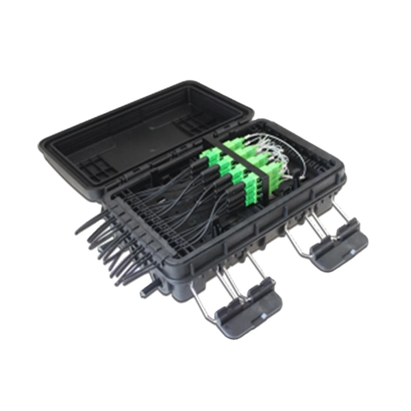
Learn how to install a fiber optic termination box step-by-step for FTTH projects. Covers mounting, splicing, routing, labeling, and testing for indoor/outdoor use. Installing a fiber optic termination box is one of those jobs that looks simple on paper, but it's easy to do. A common question we receive is: How do you use a fiber-optic termination box? We recommend using a termination box if you're ordering an assembly with more than two strands. It helps keep your connectors free from contamination and dust, while also keeping your assembly neat and organized. Check. A Fiber Termination Box, also known as a Fiber Distribution Box, is a crucial component in fiber optic networks. They also feature resistance to moisture, impact, chemical exposure. Whether you're a network technician, IT professional, or simply looking to understand fiber optic networks better, this guide will provide you with the essential knowledge for working with fiber termination box.
[PDF]

In this step-by-step tutorial, learn how to splice fiber optic cables like a pro — perfect for telecom technicians, network engineers, and field techs. more 🔧 Watch a real-time fiber optic splicing demo in action!. Fiber cable splicing is a critical step in building reliable fiber optic networks. Whether in data centers, telecom rooms, or outdoor FTTx deployments, proper splicing inside a fiber enclosure ensures low signal loss, long-term stability, and easy maintenance. This guide explains what fiber cable. In this guide, we cover the basics of fiber optic splicing, how to perform splicing using two different methods, and finally some best practices to perform good fiber splicing. What is Fiber Optic Splicing and Why is it Needed? – #1. Whether repairing a broken cable or extending a fiber run, fiber optic splicing ensures light signals travel. Regardless of your level of experience, creating high-quality, high-performance fiber optic networks requires developing your skills in fusion splicing. This guide reveals the secrets to fusion splicing with little fluff—just proven, straightforward techniques refined from years of work in the.
[PDF]
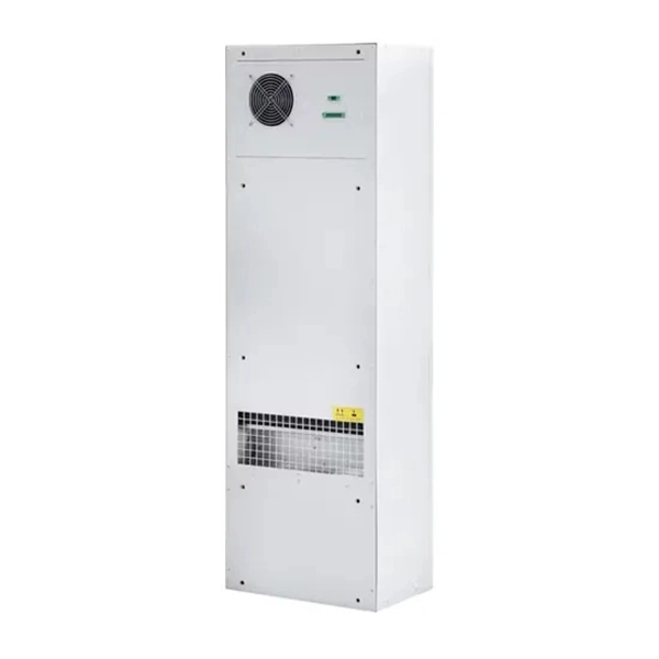
This video shows real on-site footage of electrical installation, demonstrating safe and standardized wiring methods used by professionals. more Learn how to wire a distribution box step by step!. A distribution box is the heart of any electrical system. It takes the incoming power and safely distributes it to different circuits throughout your building. Whether in a home or an industrial facility, this box keeps your electrical setup organized, functional, and efficient. However, the key to. In modern electrical systems, cable distribution boxes (also known as electrical distribution boxes or distribution boxes) play a crucial role as the key hub for managing, distributing, and protecting circuits. It serves as a central hub for distributing electricity throughout a building, ensuring that power is delivered safely and efficiently to all the required locations. Box installation: Make sure that Distribution box has been correctly installed and fixed. Material preparation: Prepare the required circuit breakers, wires, wiring ties and other materials, and ensure that they meet the design drawings and installation requirements. Location determination:.
[PDF]

This wikiHow article will teach you how to splice a cut fiber optic cable back together with a fiber optic stripper and cutter and a fiber optic crimper. Trim off any frayed or damaged ends of the cable. While a cut or damaged fiber optic cable can temporarily take your network down, it is possible to quickly fix the cable with the right tools. When fiber cables sustain damage, specialized repair techniques help restore connectivity and maintain data integrity. This comprehensive guide outlines professional fiber optic repair protocols that align with industry best practices. Adhering to precise methodologies, we can mend impaired cables. Get your fiber optic cable repair tools together. You'll need strippers, cleavers, splice trays, a splicing machine, and cleaning materials like alcohol wipes. Leave some extra cable before the damage point. It makes cutting and splicing easier. However, you don't need to panic! It can still be fixed. If you have the right tools and knowledge, you can definitely find the solution. Understanding the causes and types of fiber optic cable damage helps detect. Whether you're a network technician, IT professional, or telecom operator, you'll find practical steps, tools, and tips to restore connectivity with minimal loss. Dekam Fiber's state-of-the-art solutions, including our UltraRepair kits, make these processes accessible and reliable.
[PDF]
This guide walks you through the complete fiber installation process, from checking availability to optimizing your Wi-Fi network performance. Upgrading to fibre internet involves replacing your existing copper cables with new fibre-optic ones. This upgrade brings faster speeds and more reliable connectivity. Here is what the installation process is like: One of our technicians will visit your home, remove the old copper wiring and. If you need Fiber Optic Cable Installation in Malta or areas close by allow us to assist you by connecting you with specialized pros who can do the work you request. Step 1: Planning Before any installation begins, thorough planning is essential. This includes determining the network's requirements, such as bandwidth, distance, and the number of. This guide will explain the entire set of activities involved in installing Fiber optic cable contractors -from the early planning stage right through testing-for facility managers, IT teams, and low-voltage contractors to build high-performance networks safely and efficiently. The processes. The Fiber Optic Association, Inc. (FOA) was founded in 1995 to help develop the workforce to build the fiber optic networks to support a rapid expansion in communications and the Internet. The charter of the FOA was to promote professionalism in fiber optics through education, certification, and. We offer :- For more information email us on sales@merlin.
[PDF]

