
In this guide, we break down the two core stages of optical fiber manufacturing: preform production (shaping the precursor material) and fiber drawing (transforming the preform into thin, usable fiber). Optical fiber preforms are the starting point behind every kilometer of fiber optic cable. Though rarely seen by end users, these cylindrical glass rods serve as the base material from which high-speed optical fibers are drawn. As global communication relies more than ever on fiber networks—from. 📦 For purchasing, use the RP Photonics Buyer's Guide for fiber preforms. It provides an expert-curated supplier directory, buyer-focused technical background information, and structured selection criteria to support professional procurement decisions. During the fiber drawing process, the preform is heated and drawn into a. The production of optical fiber is a precision-driven process that transforms raw materials like silicon tetrachloride into ultra-thin, high-performance fibers capable of transmitting terabits of data over thousands of kilometers. Who invented optical fiber and when? Corning scientists Dr. Peter Schultz, and Dr.
[PDF]
In this video, I have explained and verified the Telnet & SSH configuration on an H3C Switch (Model 6520). As shown in Figure 1, the AC is a Telnet server. Make sure the network connections are available. Click the System View tab at the bottom of the page. From the navigation pane, select System > Resource. On the IPv4. To create a user on an H3C switch, you can perform this operation through a web interface or SSH. Follow the commands below to create a user: Specify the user's access level. The same CLI commands and configuration steps can also be applied to other H3C switch models. You will be in the AUX user interface if you log in through this port. 2 User Interface Number Two kinds of user interface index exist: absolute user interface index and relative user interface index. H3C S5100-SI/EI Series Ethernet Switches Chapter 1 Logging In to an Ethernet Switch 2) A relative user interface index can be obtained by appending a number to the identifier of a user interface type. The relative user interface indexes are as follows: z z. Add the specified port to the current VLAN Configure the link type of the port as Trunk type Allow the specified VLAN to pass through the current Trunk port Set the default VLAN for the trunk port Configure the link type of the port as Hybrid View the VLANs that exist on the current switch View the.
[PDF]

When it comes to testing fiber optic cables, a Visual Fault Locator (VFL) is an essential tool in your toolkit. A VFL is used to detect faults, breaks, or bends in fiber optic cables by emitting a bright red light that is visible even through the fiber's jacket. Let's dive into everything you need to know about mastering VFLs. It's a cost-effective and. Visual Fault Locator (VFL) testing is one of the most fundamental inspection methods used in FTTH, ODN, and data center environments. A VFL emits a visible red laser (typically 650 nm) that travels along the fiber core and leaks out at points of excessive loss, fiber breaks, or microbends. Although. The Fiber Visual Fault Locator Kit is an essential tool for network technicians and engineers; it provides an accurate and quick method of finding such problems as breaks, bends or faults that may affect the network's operation. It works by injecting a visible red laser light (usually in the 650nm wavelength) into the fiber. When the light encounters a fault, such as a break, bend, or bad splice, it leaks out of the fiber, making the. Conducting efficient, repeatable fiber optic cable certification requires an array of specialized test equipment: Optical Loss Test Set (OLTS) – Integrates adjustable light source and power meter for efficient, Tier-1 insertion loss testing. Visual Fault Locators – Handheld devices projecting.
[PDF]
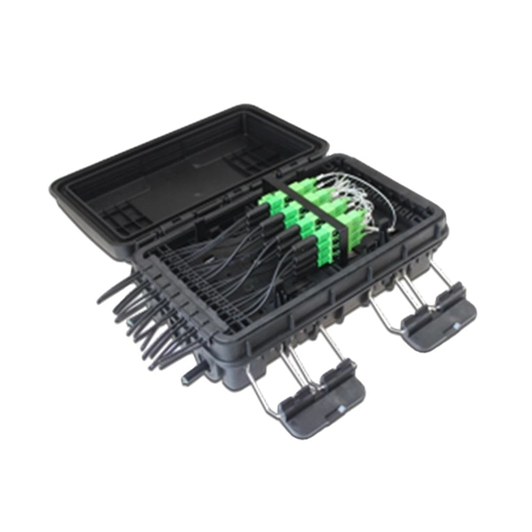
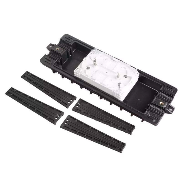
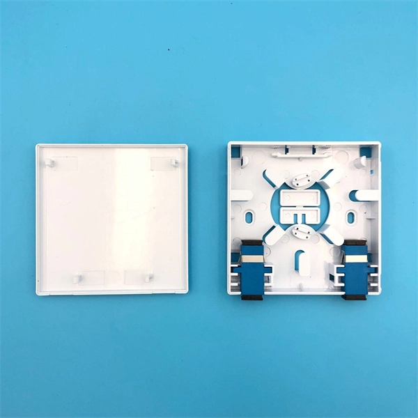
Plan your outdoor fiber installation carefully by surveying the site, choosing the right cable type, and following FOA and OSP standards to ensure reliability. Select the best installation method—direct burial, aerial, conduit, or underwater—based on your environment and. Underground cables are pulled in conduit that is buried underground, usually 1-1. 2 meters (3-4 feet) deep to reduce the likelihood of accidentally being dug up. In extreme cold climates, cables may need to be buried at greater depths where there temperatures are colder and frost penetrates to. We are Jera line, a factory that produces cable infrastructure products. FODB-8 is installed with adapters, splitters, drop cable patchcords, pole bandings, and fiber cable slack storage. Use. pport cables and splice enclosures. Cost of rack Wire Splice B x (200 (50' Mi As ve 1'-0" wide (min) concrete apron. rons shall be sloped away from box. Cost of apron o d oun. FTTP or fiber To The Premises applications have reinforced the importance of reliable and stable fiber optic terminations. Good quality fiber laying and termination systems help achieve minimal back reflection and low signal loss. They also feature resistance to moisture, impact, chemical exposure. Fiber optic cable may be installed indoors or outdoors using several different installation processes. Outdoor cable may be direct buried, pulled or blown into conduit or innerduct, or installed aerially between poles.
[PDF]

As a key parameter for evaluating data transmission accuracy, the bit error rate directly determines the reliability and stability of communication systems. This article delves into the fundamentals and testing methods of the bit error rate. A bit error occurs when a single binary digit is flipped during transmission, meaning a logical '0' is mistakenly interpreted as a '1' by the receiver, or a '1' is read as a '0'. Through the interpretation of actual test reports, it. BER is calculated by comparing the transmitted sequence of bits to the received bits and then counting the number of errors. The ratio of how many bits received in error over the total number of bits received is the BER. This ratio is affected by many factors including: signal to noise, distortion. Bit Error Rate (BER) is a crucial metric in signal processing and communication systems, measuring the frequency of errors in data transmission. It is defined as the ratio of the number of bits received in error to the total number of bits transmitted over a communication channel during a specified. In the fast-paced world of digital communication—where billions of bits travel through wires, fibres and wireless links every second—the concept of bit error rate (BER) is both fundamental and profound. It involves measuring the rate at which errors occur in a transmitted bitstream compared to the expected bitstream at the receiver end. The BER measurement helps in assessing the quality.
[PDF]
It plugs into network equipment (like switches, routers, or servers) and its primary function is to convert electrical signals from the device into light signals for transmission over fiber optic cables, and then convert received light signals back into electrical signals. People can also refer to an optical transceiver as a fibre optic transceiver or optical module. A transceiver is a mix of the words 'transmitter' and 'receiver. ' An optical transceiver includes an optical. This section explains the core IP and optical components used in traditional hierarchical networks. It helps readers understand the router, transponder, ROADM, amplifier, and management elements that form the baseline network architecture. In fiber optics, this data is sent in the form of pulses of light over an optical fiber, at very high speeds and across long distances. Essentially, these devices. Why choose Nokia for your optical network? The Nokia industry-leading optical network portfolio leverages highly vertically integrated coherent optical engines and includes the latest generation of open and flexible optical line systems, intelligent coherent pluggables, ultra power-efficient. This page provides an introduction to optical wireless networks. It compares short-range (directed and diffused) and long-range optical wireless technologies, highlighting their differences. The broadband wireless.
[PDF]

This article will give you an overview of the use cases for fiber-optic networking, some of the terms used in fiber networking, and suggestions for setting up a fiber network. Once you understand the basic concepts, you can check out my Recommended Equipment section toward. Fiber tapping is a network tap method that extracts signal from an optical fiber without breaking the connection. Tapping of optical fiber entails diverting some of the signal being transmitted in the core of the fiber into another fiber or a detector. Fiber to the home (FTTH) systems use beam. Optical fiber is a technology used to transmit data by sending short light pulses along a long fiber, which is typically made of glass or plastic. In optical fiber communication, metal wires are preferred for transmission because the signals travel more safely. Optical fibers are also resistant to. Photo: Light pipe: fiber optics means sending light beams down thin strands of plastic or glass by making them bounce repeatedly off the walls. This is a simulated image. Note that in some countries, including the UK, fiber optics is spelled "fibre optics. " If you're looking for information online. This manual covers everything about fiber optic cables, how they work, where they are used, and what is new in this area of technology. The choice of fiber optic cable depends on the specific needs of the application, as well as the.
[PDF]
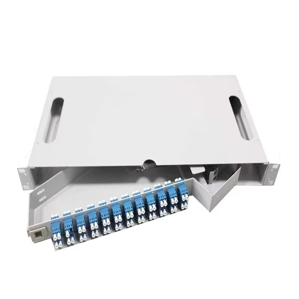
Learn how to splice 4-fiber optic cables using ODF in this complete step-by-step tutorial. Whether you are a beginner or a professional in fiber optic networking, this guide will help you splice fiber cables accurately, manage connections with ODF panels, and ensure. This complete guide explores everything you need to know about ODFs — from their structure, types, and key components, to installation best practices and modern design trends. Whether you're building a central office, data center, or FTTx distribution network, understanding the right ODF. How to Splice 4-Fiber Optic Cable with ODF | Step-by-Step Fiber Optic Splicing Tutorial. This guide demystifies ODF, exploring their design, core functions, types, and how they. An Optical Distribution Frame (ODF) is the central hub for fiber splicing, termination, patching, and cable protection in modern optical networks. It's where incoming and outgoing cables meet. It does four key things: Think of it as the central hub for your fiber network. Without it, cables get tangled. This article explores the types, components, applications, installation, and maintenance best practices, providing a.
[PDF]
This comprehensive guide will delve into the most effective practices, key considerations, and strategic approaches for designing and implementing an efficient cabling system within a data center environment. At the core of data center connectivity are fiber optic cables, which are thin strands of plastic that transmit data using light signals or wavelengths, offering unparalleled speed and efficiency. The data superhighway paved by fiber optics forms the backbone of modern data centers, ensuring rapid. An end-to-end cabling system is an ideal solution for data centers especially when time for traditional cable installation and termination is limited. Explore advanced configurations, testing protocols, and industry best practices. As the demand for data surges, these switches become more vital in sustaining networks that are efficient, scalable, and. As data centers continue to grow in complexity and scale, efficient fiber optic cabling is essential for maintaining high performance, reliability, and scalability. Proper planning and implementation of cabling infrastructure can significantly reduce downtime, improve airflow, and ensure. center hardware layout design. This map should include the cabinet placements, patch panels, hardware, port-counts, trunking locations and power access connection points. Future plans for change will be discussed, as well as the bandwidth required. infrastructure design. The design's intent is to.
[PDF]
These screws should be 1 to 1. 5 inches long to penetrate the box and embed into the center of the stud without protruding out the back. When attaching boxes to metal studs, the preferred fastener is a self-tapping or self-drilling metal screw, such as a #6 or #8 size with a pan or. These screws should be 1 to 1. All sorts of grounded electrical metal things are mounted with self-drilling or self tapping screws that do not have 32 threads. Leviton Comment: We are covering Articles 312. 10 Screws or Other Fasteners. Screws or other fasteners installed in the field. The length of the device screw varies based on the box depth and its recess from the finished wall surface. Standard installations often use screws between 1/2 inch and 3/4 inch long, but deeper boxes or those requiring adjustment spacers may necessitate screws up to 2 inches. Using a machine screw. These standard metal boxes have been secured by driving self-tapping screws through the 1/8-inch diameter mounting holes in the side of the box and into the horizontal metal stud. Code Change Summary: Changes were made to the. My plan to ground the outlet is to use a self-tapping metal screw fixed to the back of the box. Is this a proper method of connecting the outlet ground. The old boxes have tiny threaded holes at the front of the box, but they are too small for a standard machined ground screw. The threads are a 10/32" size thread. The 4020513001K.
[PDF]
On average, commercial projects range from $5,000 to $20,000 per mile underground and $40,000 to $60,000 per mile for aerial deployment. Individual business connections often cost between $15,000 and $30,000 for 100–200 network drops. Buying fiber optic installation services involves several cost components, with total price influenced by length, location, and access. The main cost drivers include trenching or aerial deployment, materials, labor hours, and any required permits. This guide presents typical price ranges in USD to. The initial cost of installing fiber optic cables can vary depending on the chosen installation method and specific project requirements. In preparing this second edition of the Fiber Deployment Cost report, Cartesian gathered inputs from a wide variety of firms building. Getting accurate cost estimates is crucial for winning fiber installation bids. Smart contractors know that underground vs aerial installation pricing varies wildly based on location and project conditions. This breakdown gives you real numbers to build better estimates. We'll show actual costs for. Home and business buyers typically see a wide range of costs for fiber optic projects, driven by distance, fiber type, conduit needs, and labor. The price can shift based on underground vs. aerial routes, equipment choices, and whether new permits are required. Some variables are less determinate.
[PDF]

This video shows you how to build a 10Gbps fiber optic network between buildings using PoE+ switches, SFP+ transceivers, and link aggregation for even higher speeds (up to 40Gbps!). Modern network infrastructure depends on fiber aggregation switches to combine several fiber optic links into one streamlined network connection. They are built to handle large amounts of data flowing through them without interruptions over long distances. more Need to transfer. With AXIS D8308 Fiber Aggregation Switch you can connect multiple Axis devices using fiber midspans over long distances. It also enables easy expansion by simply adding more fiber or network switches. Long-distance installations often require fiber optic cables to connect different sites because of. The Cisco ASR 920 Series Aggregation Services Router is a family of fixed configuration routers that enables Service Providers to provide business, residential, and mobile access services to their users. It is the Carrier Ethernet access platform providing Ethernet services. The Cisco ASR 920. This manual provides detailed instructions for the installation, operation, and maintenance of the Ubiquiti Networks UniFi Aggregation Switch, model USW-Aggregation. Fibers in these points are either spliced.
[PDF]

The Optical Time Domain Reflectometer (OTDR) is useful for testing the integrity of fiber optic cables. It can verify splice loss, measure length and find faults. The OTDR is also commonly used to create a "picture" of fiber optic cable when it is newly installed. The Contractor tasked to perform testing or splicing on any fiber optic cable will follow these testing standards to fulfill their contractual obligations. The Contractor must utilize the correct equipment and testing techniques to gain acceptance, or the work cannot be approved. Later, comparisons can be made. For every fiber optic cable plant, you will need to test for continuity, end-to-end loss and then troubleshoot the problems. If it's a long outside plant cable with intermediate splices, you will probably want to verify the individual splices with an OTDR also, since that's the only way to make. ic system. Fiber optic testing of a newly installed system not only verifies that the system meets its design requirements, but also creates a performance baseline for all future testing and troubleshooting of t at system. What is Fiber Optic Splicing and Why is it Needed? – #1. Use and Maintain Your. This guide reveals the secrets to fusion splicing with little fluff—just proven, straightforward techniques refined from years of work in the field. The guide provides the complete workflow, covering safety precautions, tool selection, fiber preparation, fusion operation, quality control, and.
[PDF]