An optical network is a communication system that leverages light to convey information across distances, encoding data into rapid flashes of light instead of relying on electrical voltage changes. At the heart of this ecosystem lies the Optical Transport Network (OTN) — a framework defined by the ITU-T (notably G. 709) that has become the foundation for modern optical communications. This method allows engineers to manage the exponential growth in global data traffic generated by. A passive optical network (PON) is a system commonly used by telecommunications network providers that brings fiber optic cabling and signals all or most of the way to the end user. Depending on where the PON terminates, the system can be described as fiber to the curb, fiber to the building or. An Optical Transport Network (OTN) is a transmission network based on wavelength division multiplexing (WDM) technology. It is a specific type of transmission network that transmits data and manages it using optical signals. OTN is built on a series of protocols, including G. It is designed to provide a high-speed, scalable, and reliable infrastructure for the transmission of data between different network nodes. While there are many subtle differences, a clear distinction between active optical networking and PON topology is PON's use of a.
[PDF]
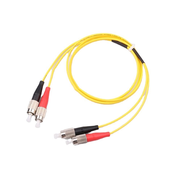
Multimode fiber optic cable has a larger core, typically 50 or 62. 5 microns that enables multiple light modes to be propagated. Because of this, more data can pass through the multimode fiber core at a given time. The maximum transmission distance for MMF cable is around 550m at the speed of. Multimode Fiber (MMF) has a core diameter, typically 50–100 micrometers, has ability to transfer multiple modes of light through the fiber core, uses lower-cost electronics (LED, VCSEL) operates at the 850 nm and 1300 nm wavelength and is used for short distance interconnections (up to 550m). This Applications Engineering Note (AE Note) discusses the criteria for properly selecting the optimal multimode fiber (MMF) for enterprise applications. Both fiber types play essential roles in today's optical.
[PDF]
The detailed steps outlined herein provide a comprehensive understanding of optical attenuator installation and adjustment. Proper execution enhances the efficiency and stability of the attenuators and the overall communication system. Fibre optic attenuators, also called optical attenuators, are passive devices used to reduce the power level of an optical signal. Assemble all necessary tools and equipment, such as a fiber cleaver, fusion splicer, optical power meter, and connector cleaning tools. These are the cornerstones of a seamless installation. Equally. Having a deep understanding of how to select a fiber optic attenuator, regardless of the type—fixed or variable—and the type of fiber and connector is critical to the durability and maintainability of a reliable network. Taking optical power measurements before installation of a fiber optic. Optical Signal Attenuation is the single greatest factor limiting the distance and performance of your network. Understanding it is crucial for anyone involved in data centers, telecommunications, or enterprise networking. In this. 📦 For purchasing, use the RP Photonics Buyer's Guide for optical attenuators. It provides an expert-curated supplier directory, buyer-focused technical background information, and structured selection criteria to support professional procurement decisions. Optical attenuators are devices that.
[PDF]
The QSFP28 optical transceiver module is designed for use in 100GBASE Ethernet throughput up to 100km over single mode fiber (SMF) using a wavelength of 1310nm via duplex LC connectors. The 100 Gigabit Ethernet signal is carried over four wavelengths multiplexing and demultiplexing of the four. 100G ZR4+ optical module provides up to 103. 12Gbps data rate using QSFP28 footprint at the wavelengths of LWDM, which is designed with digital diagnostic monitoring. All Rights Reserved. GigOptics is a leading supplier of Optical Transceivers in the USA. We offer a wide range of products at great prices with fantastic service (SFP, SFP+, SFP28, QSFP+, QSFP28, XFP, etc. Various Switch Tests: Each module is quality tested for compatibility in the multi-brand switches. Comprehensive Testing: Each. The 100GBASE-ZR4+ QSFP28 delivers 100 km reach over single-mode fiber without external amplification. With a 34 dB link budget (FEC enabled) and integrated SOA receiver, this is the longest-reach 100G option in the QSFP28 form factor. 4 LAN WDM lanes at 103.
[PDF]
When it comes to testing fiber optic cables, a Visual Fault Locator (VFL) is an essential tool in your toolkit. A VFL is used to detect faults, breaks, or bends in fiber optic cables by emitting a bright red light that is visible even through the fiber's jacket. Let's dive into everything you need to know about mastering VFLs. In the. Finding a break in a fiber optic cable can be challenging but is essential for maintaining a stable network. Common Indicators of a Cable Break Signal. Here Kingfisher's experienced engineers share their experience in best practices and procedures for fiber optic testing related mostly to installation and maintenance. We hope that by sharing our knowledge, we will help grow our industry. Please enjoy & pass on these notes. The following are key methods and techniques used for optical fiber cable line failure positioning: Visual Inspection: Perform a visual inspection of the. Locating faults in fiber optic cables requires specialized tools and techniques. Look for dirt, scratches, or damage on the connectors. Clean. To ensure the quality and continuity of fiber optic services, it is essential to identify and locate fiber optic cable faults as quickly and accurately as possible. In this article, you will learn about some of the common methods and tools for fiber optic testing and troubleshooting.
[PDF]

In this guide, we'll walk you through exactly how to splice fiber without a fusion splicer, covering the tools you need, the step-by-step process, performance specs, and common mistakes to avoid. By the end, you'll be equipped to make clean, low-loss connections in any. In this guide, we cover the basics of fiber optic splicing, how to perform splicing using two different methods, and finally some best practices to perform good fiber splicing. What is Fiber Optic Splicing and Why is it Needed? – #1. Use and Maintain Your. Optical fiber fast connectors, also known as cold connectors, are becoming increasingly popular due to their ease of use and quick installation. Unlike traditional fiber connectors that require epoxy and polishing, fast connectors use a mechanical splice to join the fibers. What is a. Three methods for connecting two fiber optic cables: fusion splicing, mechanical coupler, and splicing. Whether repairing a broken cable or extending a fiber run, fiber optic splicing ensures light signals travel. Fiber optic splicing is the art and science of joining two separate optical fibers to create a continuous light path. This process requires precision, patience, and a deep understanding of the delicate nature of optical fibers. Before any splicing can occur, whether it's mechanical or fusion.
[PDF]
To know how much wire or cable will fit on a shipping reel, enter the diameter of your cable in inches below. Our Reel Capacity Calculator will show how many feet or meters of that cable will fit on our different reels. Still have questions about reel size?. When placing an order, it's important to know how many reels you can expect. With our easy cable reel capacity calculator, you can calculate the maximum reel, spool or drum capacity. All you need is to enter the reel (drum) dimensions and the diameter of the cable. Please note that. It is often necessary to determine how much of a given cable or wire will fit onto a spool or reel. This article provides a relatively simple method to calculate the approximate maximum length if you know the cable's diameter and the reel's dimensions. Providing wire or cable on reels or spools is. An Equal Opportunity Employer to include women, minorities, veterans, persons with disabilities, color, sex, sexual orientation, gender identity, religion, origin, and genetic information. Priority Wire & Cable supplies wire & cable from the largest stock in the U. and offers same day shipping. Fiber optic cables can be custom cut by Proterial Cable America or distributor to match your required lengths for each cable run. Alternatively, you can order a reel matching the total length needed and cut your own segments as necessary.
[PDF]
The Telecoms crash, also known as the Telecommunications Bubble was a that occurred in 2001, after the bursting of the. The telecommunications industry had experienced significant growth and investment during the 1990s, fueled by the expansion of the internet and the introduction of wireless technology. Companies such as,, and had achieved enormous market valuations base.
[PDF]

The optical power meter is similar to the voltohmmeter in application but measures the optical resistance (losses measured in dBm or dBM) of a cable before and after installation and provides a comparative analysis of the splices. The range of the meter is adjustable. Regularly testing fiber optic cables helps minimize network downtime, lengthens the network's longevity, reduces maintenance requirements, and helps support network reconfiguration and upgrades. These factors significantly add to the fiber optic network's long-term performance, manageability, and. Several types of tests are commonly conducted to assess and maintain the health of fiber optic networks. Continuity testing verifies that the fiber is intact and that light can pass through from one end to the other without any blockages. These test procedures assess the physical and functional qualities of fiber optic cables, connectors, and the network as a whole. Key tests include: Effective fiber testing utilizes advanced tools such as Optical. One way to test a splice is to use an Optical Power Meter. As the components like fiber, connectors, splices, LED or laser sources, detectors and receivers are being developed, testing confirms their performance specifications and helps. Regular testing of fiber optic cables is not just a preventive measure; it's an investment in the longevity and efficiency of your network. By identifying potential issues early, you can enhance.
[PDF]
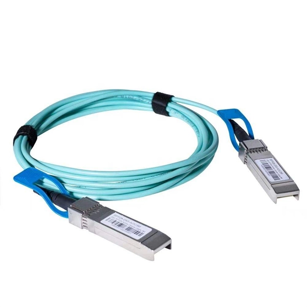
SFP transceivers are available with a variety of transmitter and receiver specifications, allowing users to select the appropriate transceiver for each link to provide the required optical or electrical reach over the available media type (e.g. or copper cables, or cables). Transceivers are also designated by their transmission speed. SFP modules are commonly available in se.
[PDF]
Typical rates range from $0. 00 per ft depending on terrain, access, and required precision for termination. Basic — 1,000 ft single-mode run indoors with minimal termination: Cable $0. 00/ft, Permits $150, Accessories $100. Total ≈. Fiber-optic cable materials typically cost $1 to $6 per linear foot, depending on fiber count and cable type. Commercial building installations with 100-200 network drops generally range from $15,000 to $30,000. Single-mode fiber costs less per foot than multimode fiber, but it requires more. Packaging should be the same as what is found in a retail store, unless the item is handmade or was packaged by the manufacturer in non-retail packaging, such as an unprinted box or plastic bag. See the seller's listing for full details. 43FedEx Ground or FedEx Home Delivery®. See detailsfor. The unit cost of fiber optic cables can vary from $0. Here's a general pricing reference: Cable TypePrice Range (USD/meter)Simplex / Duplex Indoor Cable$0. 50Multimode (OM1/OM2/OM3)$0. Main cost drivers include cable grade (indoor vs outdoor, armoured), distance, and labor for trenching, splicing, and termination. Custom-built. Uses item details. Price when purchased online Shop for Optical Audio Cables in TV Accessories. Buy products such as VANAUX Optical Audio Cable, TOSLINK S/PDIF Digital Optic Cord, Fiber Audio Cable, Gold-Plated, Nylon Braided for Home Theater, Sound Bar, TV, PS4, Xbox, PlayStation (10ft/3m) at.
[PDF]

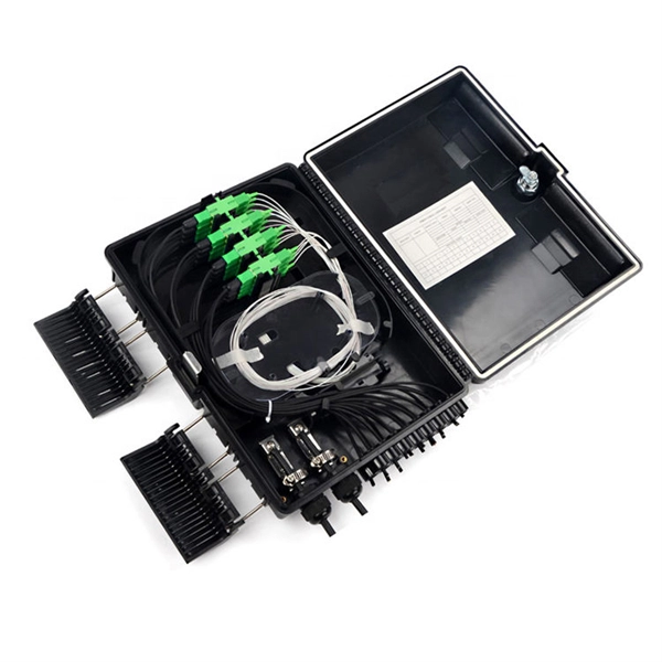
First, connect each pre-terminated fiber optic cable to the adapter panel separately, making sure the ports correspond one-to-one; then fix the fiber optic adapter panel to the front panel of the distribution box with the bend radius control clip. In general, installing the optical fiber distribution box can be divided into three steps: installing the optical fiber distribution box on the rack, introducing the optical cable into the optical fiber distribution box, and planning the optical fiber path in the optical fiber distribution box. The. Bottom installation: Select a proper installation position in the equipment room and drill four holes in the floor according to the dimensions shown in the manual. Fix the rack to the ground with expansion bolts. Top installation: Dimensions of four connection holes on the top according to the. The Optical Distribution Box (ODB) is high-density 2-in-2-out fiber box solution. Designing with a compact size of 340x220x100mm, the cabinet accommodates 1x2,1x4,1x8 and 1x16 etc. The 4 ports are sized for main cable from 9 to 16mm in diameter, along with 16 3mm cables. Accessory Kits:. Install the optical fiber distribution box on the rack. Ensure that the box is installed firmly and horizontally, and the deviation of perpendicularity is not greater than 3mm.
[PDF]

Insertion loss tells you how much weaker the signal becomes after passing through the splitter. Let's say you have a laser output at 0 dBm (which is 1 milliwatt of optical power). If you use a 1×8 splitter with ~10. 5 dB of insertion loss, the power at each output would be: 0 dBm – 10. 5. Enter excess loss from the splitter datasheet for your wavelength. Add connector and splice quantities with realistic planning losses. Include any additional component losses and an engineering margin. Enable power budget to estimate received power and margin. Press Calculate to show results above. Understanding optical splitter loss isn't just about plugging numbers into a calculator. It's about knowing what factors contribute to that loss, how manufacturers specify it, and how it impacts the overall performance and reach of your network. Ignore it, and you might find your signal too weak to. Optical insertion loss refers to the signal loss resulting from the insertion of components such as connectors or splices in an optical fiber system. Common ratios: For cascades, add losses and validate margin using the Optical Budget tool. This Fiber Optic Splitter Insertion Loss is the splitter devices loss, Considering fiber connectors or connectors+adapter insertion loss in LGX, The fiber splitter IL would be a little bigger. To make clear the basic ftth fiber splitter loss in performance, You can refer to the below loss chart.
[PDF]