In this guide, we'll break down the essentials, explore different wiring configurations, and provide you with practical tips to get your sensors up and running smoothly. So, grab your tools, and let's get started! Before we jump into wiring diagrams, let's quickly recap what fiber optic sensors are. working principle: Fiber optic sensors use the propagation characteristics of light to detect or measure various physical and chemical quantities. Here are some basic working principles of fiber optic sensors: Propagation of Light: An optical fiber consists of two parts: a core (the central part of. A Fiber Sensor is a type of Photoelectric Sensor that enables detection of objects in narrow locations by transmitting light from a Fiber Amplifier Unit with a Fiber Unit. Detection in Narrow Locations The small sensing section and flexible Fiber Unit cable enable a Fiber Sensor to. Click to download the ODiSI Fiber Optic Sensor Installation Guide. The following instructional videos explain how to install, configure, and calibrate the FiberPatrol FP400 fiber optic fence-mounted intrusion detection sensor. Copyright © 2026 Senstar Corporation. Legal | Accessibility. Surprisingly Stable Detection with Your Finger tip. Exceptionally easy operation and stabilizing technology reduce maintenance cost. If you Login / Signup, you can download the PDF of the Manual. Please note some product models not sold in Singapore may be included in the following manual (s) for.
[PDF]
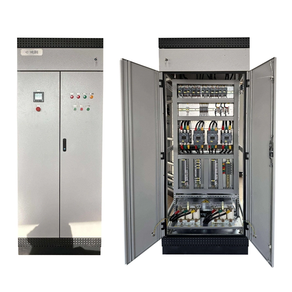
In this video, we'll walk you through the process of wiring a home distribution box with a detailed connection diagram. Whether you're an electrician or a DIY enthusiast, this guide will help you understand the basics of home electrical distribution. more Welcome to our channel! In this video. An electrical panel box, also known as a breaker box or a distribution board, is a crucial component of any electrical system. It serves as a central hub for distributing electricity throughout a building, ensuring that power is delivered safely and efficiently to all the required locations. Distribution Board or DB is an electricity supply system or a common enclosure that distributes the electrical power feed into subcircuits. It includes isolator, RCCB (Residual current circuit breaker) or RCD (Residual-current device) devices, protective fuses or MCB's (Miniature Circuit Breaker). Learn how to install a distribution box safely and correctly. Covers wiring, placement, standards, and expert tips for a compliant setup. It takes the incoming power and safely distributes it to different circuits throughout your building. Box installation: Make sure that Distribution box has been correctly installed and fixed. Material preparation: Prepare the required circuit breakers, wires, wiring ties and other materials, and ensure that they meet the design drawings and installation requirements. To understand how a breaker box works, it is helpful to.
[PDF]

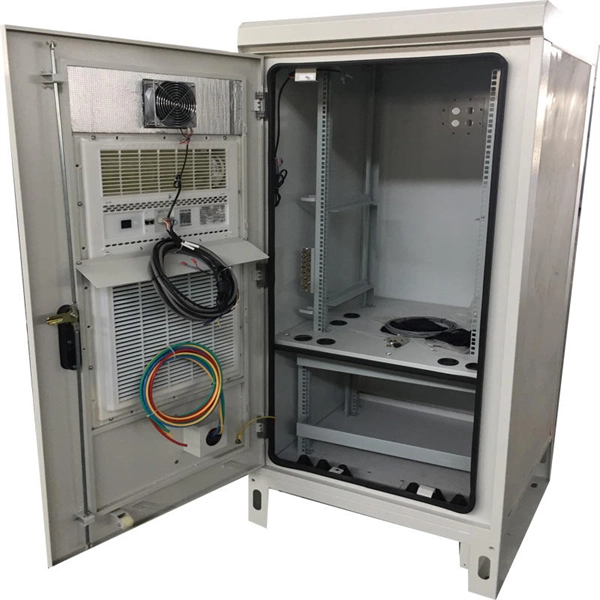
The proper installation of a distribution box involves placing it at the right height to ensure safety and convenience. 7 meters) high makes it easily accessible without the need to bend or stretch excessively. (1) Elevator driving machines, motor generator sets, controllers, and auxiliary control equipment shall be installed in a room or enclosure set aside for that purpose. This height also safeguards the box from potential. The work space shall be clear and extend from the grade, floor or platform to a height of 6 1 / 2 feet or the height of the equipment, whichever is greater. The electrical equipment itself may have a height that is less than 6 1 / 2 feet, but if it is mounted so the top of the equipment is higher. Overcurrent devices and disconnects must be located in machine or control spaces, be lockable and provide a single means to disconnect ungrounded conductors, with selective coordination for multi-elevator feeders. Conductor and wireway fill, approved flexible traveling cables and secure supports. Choose the right box based on environment (indoor/outdoor), load capacity, and durability. Check for proper IP/NEMA ratings and material quality. Ensure safe placement: install in dry, accessible areas with good ventilation and at appropriate height (typically ~1. Practice good wiring: secure.
[PDF]
This guide provides a detailed, professional procedure for installing a Residual Current Circuit Breaker (RCCB)—a device essential for protecting people from the severe danger of electric shock. The steps outlined here are fundamental to ensuring the RCCB functions. It is an electrical protective device that protects electrical circuits and devices from some electrical faults such as leakage faults, electrical shock, current unbalance due to equipment failure, etc. It works on the principle of sensing residual current which is why it is called a residual. Distribution board is a safe system designed for house or building that included protective devices, isolator switches, circuit breaker and fuses to connect safely the cables and wires to the sub circuits and final sub circuits including their associated Live (Phase) Neutral and Earth conductors. Residual-current devices, commonly referred to as RCDs, are used in many practical applications. They can be found in fuse boxes, electrical switchgears or industrial machine control systems. Therefore. To wire an RCD fuse box correctly, start by reviewing the diagram to identify each circuit and its corresponding components. Understanding the layout helps prevent mistakes and ensures safe wiring. floor in a multi storey building. The Sub distribution board is connected and supplied from the Main Distribution Board through different wires and cables rated.
[PDF]
In this video, we'll walk you through the process of wiring a home distribution box with a detailed connection diagram. Whether you're an electrician or a DIY enthusiast, this guide will help you understand the basics of home electrical distribution. more Welcome to our channel! In this video. An electrical panel box, also known as a breaker box or a distribution board, is a crucial component of any electrical system. It serves as a central hub for distributing electricity throughout a building, ensuring that power is delivered safely and efficiently to all the required locations. What is Distribution Board? Distribution board. Hey, in this article we are going to see the Single Phase Distribution Box Wiring Diagram and Connection Procedure. And all the switching and protective devices are installed in the. Are you ready to master the skill of building electrical panels? This detailed guide provides an excellent base for beginners. Learn about the essential components of panels, such as the circuit breakers and fuses that safeguard against hazards. Then, delve into complex wiring configurations. Single Phase wiring installation is the most common wiring in residential buildings. In Single Phase supply (230V in UK, EU and 120V & 240V in the US & Canada), there are two (one is Line (aka Phase, Hot or Live) and the other one is Neutral) incoming cables from the utility poles to the kWh energy.
[PDF]

Attach a ground wire from one of the threaded studs (A) at the bottom of the housing, to the mounting plate (B). The ground resistance between all system parts shall be <. The correct connection method of Distribution box grounding wire mainly includes the following steps: 1. This position is the connection point of the grounding wire in the. The National Electrical Code (NEC) lists eight specific methods to make grounding and bonding connections in Sec. Failure to install these connections properly can result in shock, fire, or, most certainly, power quality problems. Let's take a look at each one in more detail. Listed pressure. Make the most of outdoor spaces with permanent, weathersafe power. Learn our complete installation process from start to finish. Watch our video to learn more. Securing the ground wire: Secure the grounding wire to the ground bar using a grounding screw or terminal. Each DISTRIBUTION BOX and controller must be grounded. On the US market, a 5. 26 mm 2 (10 AWG) ground wire must be used, and in all other markets a 6 mm 2 must be used. Grounding of the units: Attach a ground wire from one of. Learn how to install a distribution box safely and correctly. Covers wiring, placement, standards, and expert tips for a compliant setup. A distribution box is the heart of any electrical system. It takes the incoming power and safely distributes it to different circuits throughout your building.
[PDF]

In this video, we'll show you how to connect an energy meter to a distribution board (DB) safely and efficiently. A residential electric meter box wiring diagram illustrates the connection between the utility service drop and the main breaker panel. It shows the hot wire entering the meter lugs, the neutral wire connecting to the neutral bus bar, and the essential ground wire linkage to ensure system safety. energy meter connection with distribution box How to Connect an Energy Meter to Your Distribution Box Easily Steps to Properly Connect Your Energy Meter to a Distribution Box. This prevents arc faults and ensures safety when modifying or inspecting current paths. Inside the service housing, line conductors from the utility feed typically enter through the. The wiring that links the utility company's service point to a home's electrical distribution system is the main service connection. This “meter to panel” wiring establishes the pathway for all incoming electrical power from the grid to the home. Whether you're an electrician or a DIY enthusiast, this guide will help you understand the basics of home electrical distribution. What is Distribution Board? Distribution board.
[PDF]

This video shows real on-site footage of electrical installation, demonstrating safe and standardized wiring methods used by professionals. The National Electrical Code (NEC) Section 700. 10 provides critical guidelines for the wiring of emergency systems. These systems ensure continued operation during power outages, protecting lives and maintaining functionality in key buildings. This guide breaks down the essential requirements of. Emergency system circuits supply power to critical life safety loads such as emergency lighting, fire alarm systems, fire pumps, smoke control systems, and essential communication and control circuits. Correct wiring design for emergency system circuits is essential to maintain power integrity. The general rule in 700. 10 (B) is to keep wiring from an emergency source or emergency source distribution overcurrent device to the emergency loads entirely separate from all other wiring and equipment, unless otherwise permitted in 700. 10 (B) (1) through (5). 12) of the interruption of the normal electrical supply.
[PDF]

Start by separating your Ethernet cable into two separate cables and connecting them to the back of the Ethernet cable splitter. Once the cables are securely connected, connect the other ends to your desired devices. Ensure that the cables are tightly secure and that all connections. When you need to connect multiple wired devices like computers, printers, and IP phones, but only have one Ethernet wall port, using an Ethernet splitter or network switch can expand your connectivity without rewiring. This guide explains your options and helps you choose the best solution for your. An Ethernet splitter is a small device that allows two Ethernet-connected devices to share a single cable run. It does not increase speed or create extra bandwidth. It simply divides signal pairs. This tool works best in basic setups where running another cable is not possible. An Ethernet splitter. Ethernet cable splitter wiring diagrams are essential for anyone who needs to connect multiple devices in a home or office network. With the ever-increasing popularity of high-speed internet and streaming services, providing reliable connections to multiple devices is becoming increasingly. An Ethernet splitter doesn't actually split a single Ethernet connection to provide separate internet access to two devices. Instead, it utilizes only two of the four pairs of wires within a single Ethernet cable to connect two devices, requiring two splitters for the setup to function correctly.
[PDF]
As light in fibers often does not have a well defined polarization state, it is important that a fiber-optic attenuator exhibits only a minimum amount of polarization dependence. Generally, the obtained insertion loss has some dependence on the optical wavelength. Some attenuators have a relatively strong wavelength dependence and are made for working in narrow wavelength regions, e.g. with a bandwidth of only 20 nm around a center wavelength of 1550 nm. Others are optimized for a weaker wavelength dependence, making them u. For single-mode devices, the insertion loss can not depend on the direction of propagation, as long as no non-reciprocal parts are used, as e.g. in a Faraday isolator. For multimode devices, however, some loss difference is possible in conjunction with a mode dependence. For many applications, it will not be a problem if the obtained insertion loss slightly deviates from the specification (e.g. by 1 dB), or if it slightly changes over time. Example cases, however, one may require a higher precision. Most fiber-optic attenuators exhibit a relatively high return loss (at least several dozens of decibels), i.e., there is not much light which is reflected back into the input fiber. For some sensitive applications, e.g. when using an attenuator before or after a high-gain fiber amplifier, one may have two use attenuators with particularly high retu.
[PDF]
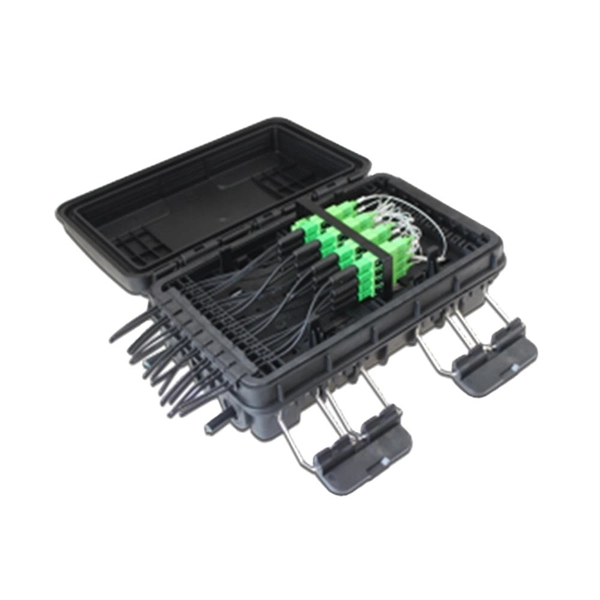
Learn how to splice 4-fiber optic cables using ODF in this complete step-by-step tutorial. Whether you are a beginner or a professional in fiber optic networking, this guide will help you splice fiber cables accurately, manage connections with ODF panels, and ensure. This complete guide explores everything you need to know about ODFs — from their structure, types, and key components, to installation best practices and modern design trends. Whether you're building a central office, data center, or FTTx distribution network, understanding the right ODF. How to Splice 4-Fiber Optic Cable with ODF | Step-by-Step Fiber Optic Splicing Tutorial. This guide demystifies ODF, exploring their design, core functions, types, and how they. An Optical Distribution Frame (ODF) is the central hub for fiber splicing, termination, patching, and cable protection in modern optical networks. It's where incoming and outgoing cables meet. It does four key things: Think of it as the central hub for your fiber network. Without it, cables get tangled. This article explores the types, components, applications, installation, and maintenance best practices, providing a.
[PDF]

In this article, you will learn the step-by-step process of testing your solar panels using a multimeter. We will cover the essential tools you need, the specific measurements to take, and how to interpret the results. A $15 multimeter and 5 minutes of testing can diagnose most solar panel problems. Measure Voc (open circuit voltage) — if it reads 0V, the panel or wiring is dead. If it reads 60–80 % of rated, a bypass diode has failed. By the end of this guide, you will be equipped with the knowledge to diagnose. Learning how to test solar panel with multimeter is useful for homeowners, technicians, farmers, and anyone using solar energy systems. A digital multimeter allows you to check voltage, current, continuity, and resistance. Fluke recommends using the Fluke 117 Electrician's Multimeter or Fluke 283 FC CAT III 1500 V Digital Multimeter to test solar modules. Here's how a technician tests solar modules with a multimeter:. A multimeter is an indispensable tool for anyone working with solar panels, allowing for accurate measurements and diagnostics. It empowers users to assess the performance, identify faults, and ensure optimal energy production. Perfect for DIY solar builders, RV owners, o. more Audio tracks for some languages.
[PDF]

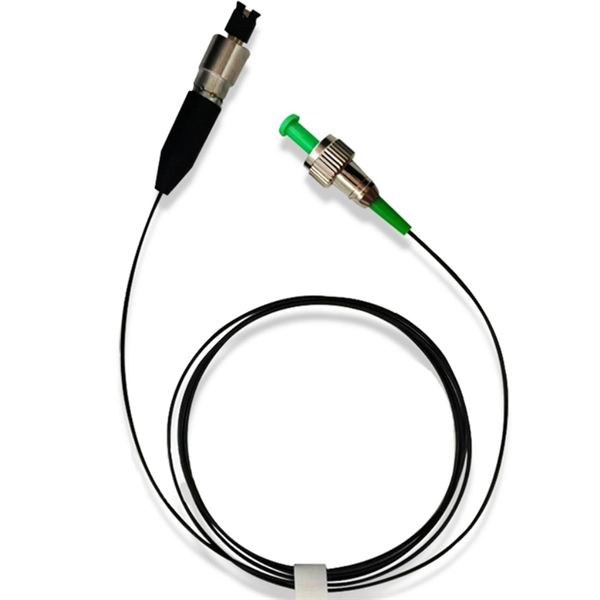
Align the fiber with the connector's guide. Ensure the fiber does not bend or twist during insertion. A proper fit prevents signal loss and enhances performance. Secure the connection using the fast connector's. Optical fiber fast connectors, also known as cold connectors, are becoming increasingly popular due to their ease of use and quick installation. Unlike traditional fiber connectors that require epoxy and polishing, fast connectors use a mechanical splice to join the fibers. In this article, we will. At the heart of any robust fiber optic network lies a crucial process: Preparing a fiber cable for termination of a connector or splice. Two types of splices are used in fiber optic cabling one is Mechanical the other is Fusion. Whether you're installing a new network, expanding an existing one, or. Optic Fiber cleaving, and mechanical splicing through very simple processes in this short series of videos. Thank you for supporting us by viewing our content. Doubts and suggestions? Leave us you. more Audio tracks for some languages were automatically generated. The primary purpose of a fast connector is to ensure a stable and reliable link. Connecting a fiber optic cable to a connector is a precise task that requires careful attention to detail, as well as some specialized tools and equipment. These terminations must be of the right style, installed in a.
[PDF]