
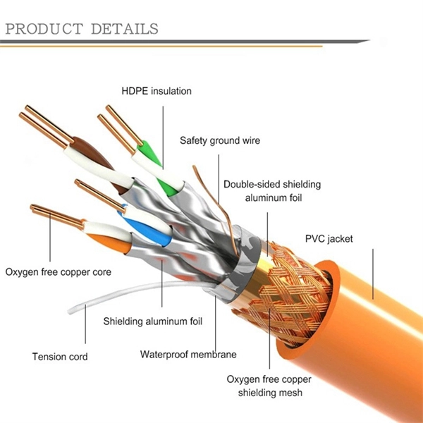
This article provides a detailed technical comparison between fiber optic and copper cables, offering a clear perspective for engineers, network architects, and procurement managers. The core distinction between the two technologies lies in the physics of data. However, the exponential growth in data demand has positioned fiber optic technology as the superior alternative for performance, scalability, and future-readiness., 10G/25G/40G/100G and beyond depending on optics and reach). Copper Ethernet scales too, but practical limits are lower and depend. The two main options are fiber optic cables and copper cables, each with its own advantages and drawbacks. Fiber optic cables are praised for their high performance and scalability, while copper cables remain a cost-effective choice, especially for budget-conscious projects and older systems. Copper wire is more susceptible to interference and has limited data capacity, making optical fiber the preferred choice for modern high-speed. Optical connectivity, utilizing fiber-optic technology, has emerged as the superior choice for modern networking, offering unparalleled performance, reliability, and scalability. For example, a typical 10 Gbps copper Ethernet link (such as Cat 6A) over 100 meters can consume approximately 5 to 8+.
[PDF]
This blog article entry considers the merits of choosing which of various low loss RF coaxial cables to use for IoT, LTE or LORA wireless applications where an external antenna is used to connect to router, gateway or terminal. The choice looks deceptively simple—pick a length, screw it on—but RF engineers know the truth: every extra meter quietly eats away at your link budget, especially once you cross 2 GHz. It's not just about length; the cable type, connector quality, and even mounting environment make a measurable. Audio generated by DropInBlog's Blog Voice AI™ may have slight pronunciation nuances. In this article, we will consider cables such as RG174, RG58, RF195. The cheap connectors have inferior dielectric between the poles as well as poorer grades of metal. The dielectric won't handle high power (KW range) as well and the center pin can more easily shift causing impedance problems if they are moved frequently. RF connectors are usually used with coaxial cables. They are designed to maintain the shielding that the coaxial design offers. The better and newer. Besides the wide range of RF connectors, Telegärtner also provides a considerable range of suitable coaxial low loss cables. Using this one-stop shopping option at Telegärtner makes your purchasing process even more efficient. The main use of low loss cables are all kinds of wireless applications.
[PDF]

Compare fiber optic and copper Ethernet cables across speed, distance, cost, installation difficulty, and use case metrics. Use the interactive scenario selector to find the right medium for your specific network — all processed locally in your browser. PoE Required?. The core difference between fiber optic and copper cables lies in how they carry data. One uses light, the other electricity—and that distinction shapes everything from speed to signal integrity. Fiber optics transmit data as pulses of light through ultra-thin strands of glass or silica. Both technologies can deliver high-speed connectivity, but they behave differently under real-world constraints such as. However, the exponential growth in data demand has positioned fiber optic technology as the superior alternative for performance, scalability, and future-readiness. This article provides a detailed technical comparison between fiber optic and copper cables, offering a clear perspective for. Fiber optic tends to be the more premium solution, while copper wiring is far more common, but why is that? What are the differences between these two cable types, and why might you want to pick one over the other? Here's everything you need to know about fiber vs. copper cables, to help you pick. Several factors are converging to drive the switch from copper to fiber – and cost is a big one. A recent investor presentation by AT&T claimed that fiber was 35% less costly to maintain than copper.
[PDF]

The primary problem encountered is signal loss, also known as attenuation. Attenuation can be due to absorption, scattering, or bending losses, affecting the quality and speed of data transmission. Attenuation in fiber optic cables is the reduction in signal strength during. To be able to judge whether a fiber optic cable plant is good, one does a insertion loss test with a light source and power meter and compares that to an estimate of what is a reasonable loss for that cable plant. The estimate, called a "loss budget" is calculated using typical component losses for. F iber optic networks rely on the efficient transmission of light signals to deliver high-speed data over long distances. However, various factors can cause signal degradation, leading to performance issues and reduced network reliability. Fiber optic signal loss, also known as attenuation, occurs. A significant signal loss in the optical fiber can cause unreliable transmission. How can we know the value of losses on the fiber link? Read on, this post will teach you how to calculate the losses in optical fiber and judge the fiber link performance. The uses various types of network cables, including multimode and single-mode fiber-optic cable. It can also break your connection. High attenuation makes your system not work well. You should fix it fast to get speed and stability back. > You can solve this with simple steps.
[PDF]
Send us your information to receive a customized quote from our dedicated customer service team. •Compact benchtop instrument for all-in-one operation optic components quickly and accurately. The system has a or LED source for multi-mode applications. With a dual two wavelengths in less than 1 second. ILM-100 system comes integration into test systems. Insertion loss is measured by utilizing the built-in, stabilized LASER or LED source in combination with the precision optical power meter. Using the OP815, dual wavelength insertion loss (IL). Desktop Insertion Return Loss Tester with color screen has stable and reliable performance, which integrates stable light source, high-precision power meter, insertion loss meter and return loss meter into one multifunction instrument. Each SMLP5-5 Kit includes an OLS4 quad Optical Light Source and OPM5 Optical Power Meter. OLS4 is an integrated two-port LED (850 and 1300nm) and laser (1310 and 1550nm).
[PDF]
In this article, we will provide you with a step-by-step guide on how to install and remove fiber optic connectors properly. Step 1: Prepare the necessary tools and materials, including the fiber optic connector, cable stripper, fiber cleaver, and lint-free wipes. HomeNetworking is a place where anyone can ask for help with their home or small office network. No question is too small, but please be sure to read the rules before asking for help. We also welcome pretty much anything else related to small networks. I have this connector on my optic fibers cable. Terminating fiber optic cables essentially means putting connectors on fiber optic cable so that you can connect the cable to various devices or network components. Think of it as the equivalent of connecting the dots in a complex puzzle; without proper termination, the whole system can break down. The fiber optic tool kit contains tools to assemble SC connectors. Required consumables are sold separately. Consumables Kit: The consumables kits for single mode and multimode connectors are show below. If the connector is broken, it might need to be replaced rather than taken out. Removing these connectors requires care to avoid damaging the delicate fibers or the connector itself. Ensure that everything is clean.
[PDF]
IEC fiber connector standards establish the global specifications for connector geometry, mating interfaces, optical performance classes, and mechanical testing across all fiber network environments. Optical connectors are used to connect optical devices to other optical devices or systems. However, each connection introduces a certain amount of insertion and return loss that. Connectors play an important role in Enterprise network architecture. They give you the power to add, drop, move, and change the network. is a small cylinder used to mount. The Fischer FiberOptic Series offers robust and faultless optical performances in any conditions. Combined with easy use, cleaning and maintenance. Tested for harsh and extreme environments (Norm IEC 61753-1 Cat. These standards ensure that passive fiber-optic components remain interoperable, stable, and. designed for diverse fiber optic applications. But what exactly sets a fibe optic connector apart in terms of its merits? The primary purpose of a fiber optic connector is to terminate the ends of fiber optic cables, ensuring they can be int rconnected reliably with minimal optical loss. After. Fiber optic technology is used in ever-increasing applications due to its inherent advantages (lower weight, EMI/RFI immunity, higher bandwidths and distances) over copper. There are many.
[PDF]

When you see “PON” on your router, it stands for Passive Optical Network. This light indicates the status of your fiber connection to the network. Passive optical networking (PON), like active optical networking, uses fiber-optic cabling to provide Ethernet connectivity from a main data source to endpoints. While there are many subtle differences, a clear distinction between active optical networking and PON topology is PON's use of a. A passive optical network (PON) is a fiber-optic telecommunications network that uses only unpowered devices to carry signals, as opposed to electronic equipment. In practice, PONs are typically used for the last mile between Internet service providers (ISP) and their customers. The purpose of an OLT is to control, convert signals and coordinate fiber optic service (FiOS) within a PON system. An ONT. Turn off the router and disconnect the power cord. Locate the optical network (PON) port on your router. Inspect the PON cable for make sure that it is correctly connected to the router. Instead of running a separate fiber strand to every home or office, a PON shares a single fiber using optical.
[PDF]

Every fiber optic patch cable has a rated attenuation and bandwidth. For example, OM1 is rated at 200 MHz·km at 850 nm and is intended for use in legacy applications. The higher OM ratings provide more speed and distance. Attenuation should remain within acceptable limits for reliable transmission. Executive Summary: Choosing the right fiber patch cable is one of the most consequential decisions in network infrastructure planning. The wrong choice — whether it's an underperforming multimode grade or an unnecessarily expensive singlemode run — can either cripple your network's reliability or. Fiber optic patch cords are key components for efficient, low-loss optical signal transmission between devices and fiber optic cabling links. One or both ends of the patch cord are equipped with standardized fiber optic connectors, and common interfaces include LC, SC, FC, ST, etc. They are manufactured and tested in compliance with TIA 604 (FOCIS), IEC 61754 and YD/T industry standards. OM1, OM2, OM3, OM4, OM5 or OS2 fiber types are available to meet the demand of. Fiber optic patch cables are ideal for supporting high speed telecommunication network fiber applications. They are lengths of optical fiber terminated with connectors on both ends. Their job is to connect two optical devices, like switches, routers, or optical transceivers that communicate.
[PDF]
Picking up the best router for fiber internet isn't just about going to the market and choosing one of the best wireless routers. Instead, you need to carefully look at its specs, performance, and the type of securit.
[PDF]
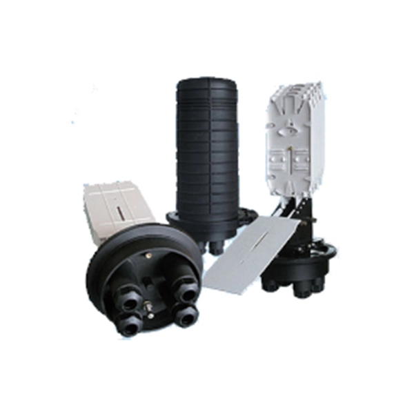
Optical Fiber Cable & Accessories Price in Nepal, Kathmandu. Buy with best and reasonable price @ ITShop Nepal. Nepal - Shop for Best Online at Daraz. np Wide Variety of fiber optic box. Great Prices, Even Better Service. Made of brand new materials, sturdy and durable, resistant to impact, corrosion, sealed and waterproof, safe and worry free Engineered for outdoor use, this junction box showcases a robust waterproof design, safeguarding critical fiber optic connections against harsh weather and ensuring reliable. Optical Fiber Cable & Accessories Price in Nepal, Kathmandu. SÜRGÜLÜ PATCHPANEL SC UPC DUBLEX 24XADAPTÖR 48XPIGTAIL RAL7035 1u 19” MEK. GJS-901-2 fiber optic splice closures (FOSC) are used to distribute, splice, and store the outdoor optical cables which enter and exit from the ends of the closure. There are two connection ways: direct connection and splitting connection. Applicable to situations such as overhead, man-well of. vianet: Vianet Communication Ltd. is a leading Internet & TV service provider in Nepal. Since 24 years, Vianet Communication has always remained at the forefront, providing reliable and affordable Fiber Broadband Internet Services.
[PDF]
Fiber testing is the process of verifying the performance of optical fiber cabling. This process includes a range of tests and measurements such as insertion loss, optical return loss, and fiber length. It encompass.
[PDF]
Compared to conventional metallic cables, optical fiber provides an advantage of low loss (~ 0. 2dB/km) and wide bandwidth (several hundred MHz to THz) to enable long-distance, high-capacity communication. Fiber-optic communication is a form of optical communication for transmitting information from one place to another by sending pulses of infrared or visible light through an optical fiber. The light is a form of carrier wave that is modulated to carry information. Fiber is preferred. It was almost a century later before optical-based communication was put to practical use, thanks in large part to the invention of optical fiber and lasers. A laser's stable, highly directional beam of light (emitted from tiny semiconductor windows that measure just a few hundred thousandths of a. In 2020, we celebrated the 50th anniversary of the invention of low-loss optical fiber — an innovation that has transformed the way we connect and that lies at the cornerstone of our communications revolution. In a Corning lab on a Friday afternoon five decades ago, a single strand of glass and a. Fibre optics and optical communications is the use of thin strands of glass for sending information encoded into light over long distances. Total internal reflection prevents light inserted into one end of the fibre from escaping through the sides. Transferring information optically in this way.
[PDF]


