
Watch the step-by-step installation of an electrical panel (DB Box) by a professional! This video showcases the process of safely wiring and setting up a distribution board for efficient power management. Whether you're an electrician, engineer, or DIY enthusiast, this. An electrical distribution box, also known as a power distribution box, panelboard, or consumer unit, is the core of an electrical system. It serves as a central hub for distributing electricity throughout a building, ensuring that power is delivered safely and efficiently to all the required locations. In this video, we'll walk you through the step-by-step process of installing a distribution board (also known as a breaker panel) safely and efficiently. It receives power from the main electrical supply and divides it into separate circuits, each. A distribution box is the heart of any electrical system. It takes the incoming power and safely distributes it to different circuits throughout your building. Whether in a home or an industrial facility, this box keeps your electrical setup organized, functional, and efficient. To understand how a breaker box works, it is helpful to.
[PDF]

Mount individual circuit breakers in the designated positions within the distribution box. Each breaker should match the current rating and type required for its specific circuit. Ensure proper connection to the busbars and secure mounting to prevent loosening over time. Correct wiring methods for circuit breakers within distribution boxes are fundamental to ensuring electrical safety and compliance with established codes. The distinction between 1P and 2P circuit breakers plays a pivotal role in determining the appropriate protection level for various circuits. This guide shows you how to organize circuit breaker wiring properly. You will learn to build a safe, efficient, and professional electrical system today. Circuit breaker wiring configurations involve organizing main switches, busbars. Circuit breakers, as important components in distribution boxes, can protect circuits from the effect of overload and short circuits. It serves as a central hub for distributing electricity throughout a building, ensuring that power is delivered safely and efficiently to all the required locations. We'll also look at whether it's good enough for your home, and what to do if your panel needs an upgrade. We want to help keep your home powered safely and. A breaker box, also known as a circuit breaker panel, is an essential component of any electrical system. To understand how a breaker box works, it is helpful to.
[PDF]

When a circuit breaker keeps tripping, the cause usually falls into one of three categories: overloads, short circuits, or ground faults. The key is knowing what's driving each one so you can troubleshoot it correctly. This comprehensive guide, compiled by ELECO's technical support team based on decades of global field experience, provides a clear, actionable roadmap to identify and solve the five most common causes of frequent tripping, saving you time and ensuring compliance on any international project. The bottom line: A tripping breaker means your electrical system is doing exactly what it's supposed to do. Now we need to figure out why. Understanding which one you're dealing with helps you know if this is something you can handle or if you need. Circuit breakers serve as your home's electrical guardians – they automatically cut power when detecting dangerous conditions. Occasional tripping is normal protection behavior, but frequent tripping signals underlying issues needing attention. It's a typical issue. Below, you'll find reasons why this occurs and tips to avoid it moving forward. Get a handle on your circuit breaker problems! Circuit breakers are protection.
[PDF]
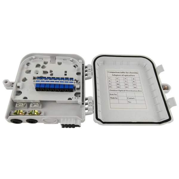
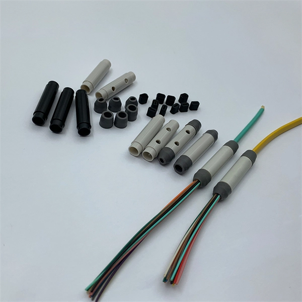
Designed to provide a clean, secure, and accessible termination point for indoor fiber connections, these outlets ensure optimal signal quality and minimal interference in residential and commercial environments. As fiber-to-the-home (FTTH) and fiber broadband continue to replace traditional copper infrastructure, the Fiber Optic Socket Wall Outlet has become an essential component of modern optical networks. These outlets act as the key connection point between your fiber optic cables and the devices that require fast, stable internet. A fiber wall socket (also called an optical termination outlet or FTTH outlet) is the critical endpoint where your home's fiber optic cable connects to the Optical Network Terminal (ONT). It ensures a clean, stable interface between the ISP's fiber network and your router—impacting speed, latency. These outlets, also known as fiber wall sockets or fiber optic outlets, play a crucial role in facilitating the transmission of data over long distances at incredible speeds. Splice holder is included. The optical trunk outlet is designed for installation in Schneider/Thorsman 80mm ducts. Trunk outlet for fiber optics delivered with adapter and pigtails.
[PDF]
Dual door fiber enclosures provide our highest level of distribution panel security. They give you the option to separately lock the network and distribution doors for more control over panel access. The second doo.
[PDF]

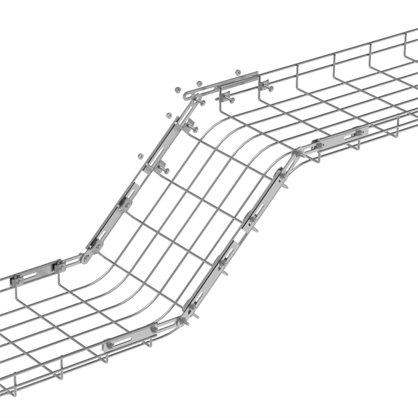
Cable tray pricing depends on materials, coatings, size, supplier margins, and order quantity —plus hidden costs like shipping and installation. This guide breaks down everything buyers need to know, from price trends to cost-saving tips. Cable trays are vital in electrical installations, providing secure pathways for power, communication, and control cables across residential, commercial, and industrial settings. Understanding the cable tray installation cost per meter is essential for effective budget planning. The average cable tray price per meter ranges from $2 to. For the best experience on our site, be sure to turn on Javascript in your browser. We offer complete kits to provide you with cable tray ready to install under new or existing raised floors based on the unique requirements at your facility. The cable tray installation price varies significantly depending on the type of cable tray selected. Choosing the right cable. The wire mesh (or basket) trays are made of fine steel wire welded to form a tray. These are the lightest and most affordable ones to purchase. They can be used wherever there are numerous small internet cables in the data centers or the offices. The price is based on standard length of the cable tray which is 2.
[PDF]

A 24-port patch panel is a networking device that allows for the organization and management of incoming and outgoing network connections. It acts as an interface between different devices such as computers, switches, and routers, allowing for easy connectivity and communication. This guide explains how to use a 24-port patch panel to manage copper and fiber cabling in a small LAN, how to choose between different patch panel types, how to design your cabinet layout, and why a patch panel is still irreplaceable in 2026. What is a Patch Panel and Why it Matters in 2026? A. Choosing a 24-port patch panel is crucial for efficiency. Learn how it enhances network capabilities. Typically, patch panels are available in a huge number of port densities from 12. In this article, we will define what a patch panel 24 port is, explain its purpose, and discuss why it is a crucial component in organising network cables. A patch panel 24 port is a device used in network cabling to connect and organise multiple network cables in one central location. It is a. Choose a 24-port patch panel when you care about clean labeling, comfortable “finger room,” and fast moves/adds/changes—especially if technicians touch the rack often and you want straightforward port-to-port mapping (Panel 01–24 ↔ Switch 01–24). Choose based on port density, cabinet space.
[PDF]

In this article, you will learn the step-by-step process of testing your solar panels using a multimeter. We will cover the essential tools you need, the specific measurements to take, and how to interpret the results. A $15 multimeter and 5 minutes of testing can diagnose most solar panel problems. Measure Voc (open circuit voltage) — if it reads 0V, the panel or wiring is dead. If it reads 60–80 % of rated, a bypass diode has failed. By the end of this guide, you will be equipped with the knowledge to diagnose. Learning how to test solar panel with multimeter is useful for homeowners, technicians, farmers, and anyone using solar energy systems. A digital multimeter allows you to check voltage, current, continuity, and resistance. Fluke recommends using the Fluke 117 Electrician's Multimeter or Fluke 283 FC CAT III 1500 V Digital Multimeter to test solar modules. Here's how a technician tests solar modules with a multimeter:. A multimeter is an indispensable tool for anyone working with solar panels, allowing for accurate measurements and diagnostics. It empowers users to assess the performance, identify faults, and ensure optimal energy production. Perfect for DIY solar builders, RV owners, o. more Audio tracks for some languages.
[PDF]

Mount individual circuit breakers in the designated positions within the distribution box. Each breaker should match the current rating and type required for its specific circuit. Ensure proper connection to the busbars and secure mounting to prevent loosening over time. When opening the distribution box, several different brands of circuit breakers are installed inside. It seems that the sizes match and the installation is fine, and this. The feeder amp rating is sized based on the sum of the amp rating of the largest branch protective device plus the full-load currents of the other loads. This value is added to the full load currents of the. Finding the right circuit breaker for your electrical panel is crucial to ensure safety, performance, and code compliance. Not all breakers are interchangeable across different panel brands – each manufacturer designs its breakers and panels as a matched system. Using a breaker that isn't made or. In industrial power distribution systems, cable distribution boxes (also known as power distributor boxes, distribution electrical boxes, or electrical power distribution boxes) are the core hub of power transmission, branching, and protection. You lower the chance of circuits getting too hot or overloaded when you pick the right box for your needs. A single circuit breaker installation mistake can cost your facility thousands in downtime, equipment damage, or worse—put lives at risk.
[PDF]
High-definition temperature sensing based on the natural Rayleigh backscatter in optical fiber delivers a virtually continuous line of temperature measurements with sub-millimeter spatial resolution. 1. Map temperat.
[PDF]

RCCBs (Residual Current Circuit Breakers) should be installed in key areas of your home's electrical system for maximum safety. The best place to install an RCCB is in the distribution board (DB box), which controls the electrical circuits throughout your home. This location ensures that the RCCB protects the entire electrical system by monitoring the current flow throughout. For added protection, you can also. A residual-current device (RCD), residual-current circuit breaker (RCCB) or ground fault circuit interrupter (GFCI) is an electrical safety device, more specifically a form of Earth-leakage circuit breaker, that interrupts an electrical circuit when the current passing through line and neutral. The primary function of an RCD is to monitor the electrical current flowing in a circuit and quickly disconnect the power supply if it detects an imbalance current (leakage of current to ground) between the live and neutral conductors. An RCD is essentially a current-operated ELCB and is commonly. RCCB Definition: A Residual Current Circuit Breaker (RCCB) is defined as a safety device that detects and interrupts a circuit when there is a leakage current to the ground. It can swiftly disconnect the circuit when a fault current happens and prevent wiring damage. In this article, we explain what an RCBO is and how it.
[PDF]
Key cost drivers include panel amperage, indoor vs outdoor location, wiring length, and whether a full panel upgrade or rerouting is needed. Buyers typically pay for a full panel replacement, including labor, materials, and permits. The article outlines cost ranges, per-unit pricing, and practical. Typical cost ranges for replacing a distribution box or service panel in the United States vary widely based on panel size, amperage, labor, and whether a full service upgrade is needed. This article outlines the cost factors, price ranges, and practical budgeting advice for a U. The price depends on electrical code upgrades, permit. Check with a local pro for your specific job. The amperage your home needs and the type of panel you choose will determine your final project cost for the replacement. You should budget for permits. The average cost to replace a breaker box is $1,475 with most homeowners spending between $1,287 and $1,707. A low-amp subpanel costs from $500 to $1,000 while a 200-amp panel upgrade runs up to $4,000. Total costs depend on the type of home, the number of circuits, and the amperage. Our homes are. Enter panel size and installation cost details to estimate the total cost of installing an electric panel. Upgrading or replacing an electrical panel is a significant investment, and understanding the costs involved is crucial for homeowners and contractors alike. Our Electrical Panel Cost.
[PDF]
Choose the right box based on environment (indoor/outdoor), load capacity, and durability. Check for proper IP/NEMA ratings and material quality. Ensure safe placement: install in dry, accessible areas with good ventilation and at appropriate height (typically ~1. Practice good wiring: secure. An electrical distribution box, also known as a power distribution box, panelboard, or consumer unit, is the core of an electrical system. It has three categories: residential, commercial and industrial electrical distribution boxes, all of which play important roles in their respective electrical. When you install a distribution box, you need a variety of tools to get the job done safely and efficiently. To install distribution box systems, you'll use hand tools such as screwdrivers and pliers. Wire strippers are essential when you install distribution box wiring. A measuring tape and. This guide offers an in-depth exploration of installing electrical distribution boards, highlighting essential steps, safety measures, and the integration of business intelligence tools to optimize your work. Just like travelers need clear pathways and safety protocols, your electrical circuits need proper management to prevent chaos. The National Electrical Code (NEC) requirements might seem like bureaucratic.
[PDF]

