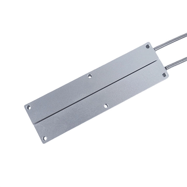
Fiber optic terminal boxes provide functions such as input, branching and splicing of optical fiber cables. Through the connectors and splicing boxes in the terminal box, optical fibers can be quickly connected and repaired. Serving as a critical connection point, FTB facilitates the termination, splicing, or connection of fibers from various cables to other network devices such as switches, routers, or Optical Network Terminals (ONTs). It aids in splicing, splitting, storing, and managing fibers within the appropriate. The optical fiber terminal box is the terminal joint of an optical cable, one end of which is an optical cable, and the other end is a pigtail, which is equivalent to a device that splits an optical cable into a single optical fiber. A fiber pigtail is a specific hardware connection used for cable termination. It is a small enclosure that can house and protect the fiber optic cables, splices, and connectors. The optical fiber termination box and optical fiber splice box serve distinct purposes and are not interchangeable.
[PDF]
A photonic integrated circuit (PIC) or integrated optical circuit is a microchip containing two or more photonic components that form a functioning circuit. This technology detects, generates, transports, and processes light. Photonic integrated circuits use photons (or particles of light) as. architecture and performance of several generations of InP-based PICs. Increased complexity in chip functionality has resulted in a need for increased fabricati n complexity from III-V epitaxy, through wafer fab, die fab, and test. Through continuous learning and improvement, Infinera has. Photonic integrated circuits (PICs) use light (photons) to transmit information, whereas traditional integrated circuits use electricity (electrons), enabling faster signal propagation. Whereas an electronic integrated circuit.
[PDF]
1x9 transceivers are the earliest and oldest-style optical modules. Initially created in the 1990s, they aimed at 100M/1G Ethernet, Fibre Channel, ATM, FDDI, SDH/SONET, and video applications. Then, they were gradually replaced by more advanced and intelligent GBICs, SFPs . Next, we will introduce the three main features of the optical module: The package form is the most important feature of the optical module. The earliest package form was 1*9, and then GBIC, SFF, SFP, Xenpak, X2, XFP, etc. came one after another. Due to the limitations of the era, the 10G optical. An optical module is a typically hot-pluggable optical transceiver used in high-bandwidth data communications applications. The unsung heroes behind this "data voyage" are optical modules—the "optical communication translators" that precisely convert electrical and optical signals. From. Before the 1990s, there was no concept of the optical transceiver industry, and equipment manufacturers independently designed and developed optical transceivers with no uniform standards for size and mechanical interfaces, resulting in poor compatibility and connectivity issues for telecom.
[PDF]
The SFP-1040-WB is a BiDirectional single fiber strand 10G SFP+ optical module using Tx:1330nm and Rx:1270nm wavelengths. The transceiver supports all 10G rated speeds for Ethernet, SONET, SDH or Fibre Channel networks. SFP-1040-WB must be paired with the SFP-1040-WA model to have an operational. The SFP-1040-Wx series single mode transceiver is small form factor pluggable module for duplex optical data communications such as 10GBASE-ER/EW defined by IEEE 802. It has the SFP+ 20-pin connector to allow hot plug capability. All modules satisfy class I laser safety requirements. Digital diagnostics functions are available via a 2-wire serial. The SFP-1040-Dxx is a DWDM 10G SFP+ optical module. It is available for all 45 DWDM 100GHz ITU grid wavelength channels. The transmitter section uses a 1550nm EML, which is class 1 laser compli Rate Select 0, optionally controls SFP+ module recei e Select 1, optionally controls SFP+ module.
[PDF]
The Open Systems Interconnection (OSI) model is a developed by the (ISO) that "provides a common basis for the coordination of standards development for the purpose of systems interconnection." In the OSI reference model, the components of a communication system are disting.
[PDF]
An optical module is a typically hot-pluggable optical transceiver used in high-bandwidth data communications applications. Optical modules typically have an electrical interface on the side that connects to the inside of the system and an optical interface on the side that connects to the outside world through a fiber optic cable. The form factor and electrical interface are often specified by an int. Electrical Interface TypesThere have been multiple variants of the electrical interface of optical modules that have been used over the years. The earliest forms of optical modules had an analog electrical interface. In the transmit dir. Many different forms of optical modulation and multiplexing have been employed in optical modules. The most common modulation technique historically has been or NRZ.
[PDF]
GYTA is an outdoor stranded loose tube fiber optic cable with aluminum tape armor (indicated by the “A” in GYTA). It is designed for aerial and duct installations but is not recommended for direct burial. It provides an excellent balance of moisture protection and mechanical flexibility, making it the preferred choice for duct and aerial backbone networks. Perfect for long-distance communication. We manufacture high quality products according to European and US standards. The aluminum. Outdoor Duct Optical Cables are strands of specially designed fiber optic cable that are ideally suitable for deployment in underground conduits or ducts. This type of cable guarantees total security for optical fibers while providing long-distance, high-speed data transmission. We supply GYTA fiber optic cable from 2 fiber cores to 288 fiber cores. Both single mode type and multimode types are available. precise control for fiber excess. GYTA fiber optic cable is an outdoor loose tube cable that uses aluminum tape armor for additional mechanical protection. This cable design is commonly installed inside underground ducts or conduits where fiber cables require protection from external pressure and environmental conditions. It is known for its high tensile strength, high flexibility, and excellent transmission performance. In this article, we will discuss the characteristics of the GYTA optical cable.
[PDF]
Optical cable junction boxes play a crucial role in connecting and protecting optical fibers, directly influencing the quality and lifespan of optical cable routes. Optical cable splice boxes protect the splicing parts of optical fibers from various hazards, such as water seepage due to adverse. Optical cable junction boxes play a crucial role in managing and organizing fiber optic networks. It serves as a termination point for fiber optic cables, providing protection and distribution of the optical fibers while ensuring efficient signal transmission. Utilizing an optical junction box can significantly enhance your. Optical cable splice box is a popular name, its scientific name is optical cable splicing box, also known as optical cable splicing package, optical cable splicing package and gun barrel. These boxes are designed to house and protect fiber optic splices and terminations, ensuring that the delicate fibers are safeguarded from.
[PDF]
An optical line termination (OLT), also called an optical line terminal, is a device which serves as the service provider endpoint of a passive optical network. It provides two main functions: to perform conversion between the electrical signals used by the service provider's equipment and the fiber optic signals used by the passive optical network.to coordinate the multiplexing between the conversion. FeaturesOLTs include the following features: • A downstream frame processing means for receiving and churning an cell to generate a downstream frame, and converting a parallel dat. Most vendors integrate an entire fiber optic management system for ISPs to manage OLTs as well as client ONTs and as such are not interoperable. • • BT-PON.
[PDF]

An optical receiver is an electronic device that detects and converts optical signals into electrical signals. The primary function of an optical receiver in digital TV setups is to facilitate the transmission of high-quality audio signals between. In this architecture, optical fiber carries signals from the headend to distribution nodes across long distances, after which coaxial cable completes the final delivery to subscribers. He oversaw the day-to-day operations of the site to ensure readers have the most up-to-date information on everything from operating systems to gadgets. Prior to his current. othing beats surround sound for movies and TV — and surround sound starts with a home theater receiver. But a receiver can give you a lot more than that. During my time as a Crutchfield Sales Advisor, I helped many people choose the receiver that worked best for them. They are a step above the previously used analog audio outs. The most common types are optical and coaxial. The rest of this article will delve into how digital audio output works, how its types differ, and. When it comes to enhancing your home entertainment experience, connecting your optical TV cable to your home theater system is an essential step that can significantly elevate your audio-visual enjoyment. This guide will walk you through the process in detail, ensuring that you have all the.
[PDF]
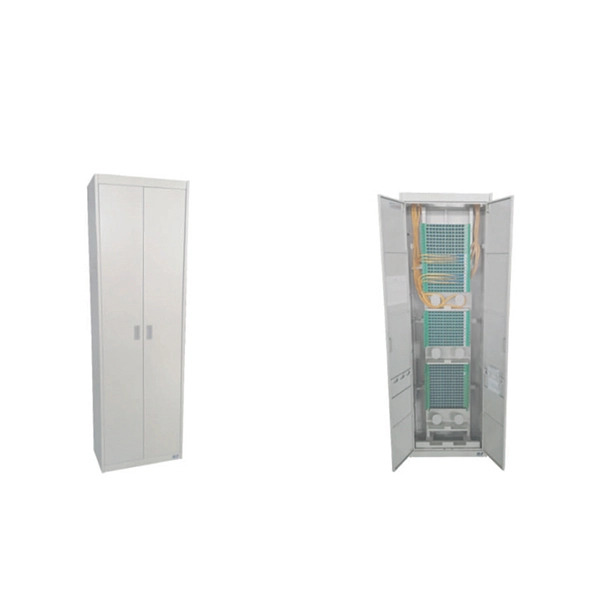
A distribution box, also known as a fiber distribution hub or optical distribution box, is a larger enclosure designed to manage and distribute fiber optic cables to multiple endpoints. It serves as a central point for connecting and organizing numerous fiber optic. Although all three are related to fiber connection and management, their installation locations, functional roles, and positions within the network architecture are fundamentally different. Confusing these devices may lead to non-standard cabling at best, and serious challenges in network. In modern FTTH (Fiber to the Home) and optical communication networks, three types of fiber distribution products are widely used: Splitter Distribution Box, ODF (Optical Distribution Frame), and Fiber Terminal Box. The functions of the four connectors can be. First, let us learn the common point among ODF, fibre optic termination box and fiber optical distribution box, actually, they have similar function, we sort out them as following 4 aspects: 1. fiber termination and optical signal splitting 4. What is the difference between these fiber boxes.
[PDF]

RFP Publishing Period: from November 12th, 2025 to 14h00, November 26th, 2025 (GMT+6:30), during MYTEL's office hours — from 8h00 to 17h30, Monday to Friday. 61-63, Zoological Garden Rd., Dagon Township, Yangon, Myanmar. We have identified 63 global optical fibre cable tenders from the public procurement domain worldwide. View the latest global tenders for optical fibre cable from Africa, the Americas, Asia, Australia, Europe, the Middle East, and other countries. Find global tender information, RFPs, RFQs, ICBs. Mytel Announcement on Invitation to Bidding No. RFP 134/2025/MYTEL-OPTICALCABLE – “Purchase OPTICAL CABLE for Mytel”. Requesting Party: TELECOM INTERNATIONAL MYANMAR CO., LTD. Tender For Provision of Fiber-optic internet services for OCHA in Sudan., communication channel rental services (fiber-optic communication channel rental services in the city of makinsk. Please click here to see the Current Opportunities. Procurement of Furniture and Equipment for the support to operationalize Public Procurement Act. Are you searching for the latest Fiber Optic Cable Tenders from trusted sources across the globe? Tender Impulse is the go-to tender website for businesses seeking verified and timely updates on public tenders, government tenders, and business tenders in a wide range of sectors.
[PDF]

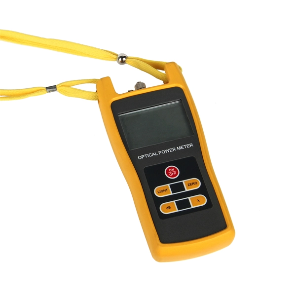
Insertion loss tells you how much weaker the signal becomes after passing through the splitter. Let's say you have a laser output at 0 dBm (which is 1 milliwatt of optical power). If you use a 1×8 splitter with ~10. 5 dB of insertion loss, the power at each output would be: 0 dBm – 10. 5. Enter excess loss from the splitter datasheet for your wavelength. Add connector and splice quantities with realistic planning losses. Include any additional component losses and an engineering margin. Enable power budget to estimate received power and margin. Press Calculate to show results above. Understanding optical splitter loss isn't just about plugging numbers into a calculator. It's about knowing what factors contribute to that loss, how manufacturers specify it, and how it impacts the overall performance and reach of your network. Ignore it, and you might find your signal too weak to. Optical insertion loss refers to the signal loss resulting from the insertion of components such as connectors or splices in an optical fiber system. Common ratios: For cascades, add losses and validate margin using the Optical Budget tool. This Fiber Optic Splitter Insertion Loss is the splitter devices loss, Considering fiber connectors or connectors+adapter insertion loss in LGX, The fiber splitter IL would be a little bigger. To make clear the basic ftth fiber splitter loss in performance, You can refer to the below loss chart.
[PDF]