CWDM uses a multiplexer to divide the light wavelengths into different channels, each carrying a separate data stream. The channels are combined and transmitted over a single fibre optic cable. At the receiving end, a demultiplexer separates the wavelengths into the original. Coarse Wavelength Division Multiplexing (CWDM) is an optical networking technology that increases the bandwidth of existing networks. Learn all about CWDM, how it differs from DWDM, and whether a CWDM solution is right for your business's network. What is Coarse Wavelength Division Multiplexing?. In fiber-optic communications, wavelength-division multiplexing (WDM) is a technology which multiplexes a number of optical carrier signals onto a single optical fiber by using different wavelengths (i., colors) of laser light. This technique enables bidirectional communications over a. In that effort, what is CWDM Technology? CWDM (Coarse Wavelength Division Multiplexing) is a powerful fiber optic solution for high-speed, long-distance networking. It's one of several fiber optic cable choices, and it can fill many roles.
[PDF]

Locating and repairing faulty Dense Wavelength Division Multiplexing (DWDM) network links quickly, and without disrupting existing traffic, is the key to avoiding excessive downtime or SLA penalties. With the commissioning and expansion of dense wavelength division multiplexing equipment in various backbone communications. Backbone network will use dense wavelength division multiplexing equipment as the main bearer channel for 10 Gigabit metropolitan area networks, NGN bearer networks, the. DWDM Network Troubleshooting and Maintenance DWDM (Dense Wavelength Division Multiplexing) systems can experience various complex problems that affect performance. Here are some typical issues: 1. Single-mode optical fiber communication has evolved to improve network reach (distance), innovative modulation formats have increased carrying capacity, and DWDM has. Dense wavelength division multiplexing (DWDM) is a fiber-optic transmission technique that employs light wavelengths to transmit data parallel-by-bit or serial-by-character. This tutorial addresses the importance of scalable DWDM systems in enabling service providers to accommodate consumer demand. 📦 For purchasing, use the RP Photonics Buyer's Guide for wavelength division multiplexing. It provides an expert-curated supplier directory, buyer-focused technical background information, and structured selection criteria to support professional procurement decisions. Wavelength division.
[PDF]

Normal WDM (sometimes called BWDM) uses the two normal wavelengths 1310 and 1550 nm on one fiber. Coarse WDM provides up to 16 channels across multiple transmission windows of silica fibers. Dense WDM (DWDM) uses the C-Band (1530 nm-1565 nm) transmission window but with denser. In fiber-optic communications, wavelength-division multiplexing (WDM) is a technology which multiplexes a number of optical carrier signals onto a single optical fiber by using different wavelengths (i., colors) of laser light. This technique enables bidirectional communications over a. This section contains examples of wavelength division multiplexing (WDM) circuits. Wavelength division multiplexing is a method of modulating multiple signals at different wavelengths (channels) to transmit them on a single waveguide or fiber. This guide delves into the principles, types, applications, and future trends of WDM. We explain the different types of WDM and how WDM-enabled optical networks can help your business. The concept involves sending multiple independent data streams down a single strand of fiber, much like transforming a single-lane road into a. Wavelength Division Multiplexing (WDM) is a technique in fiber-optic communication systems that enables multiple optical signals with different wavelengths to be combined, transmitted, and separated over a single optical fiber. This allows multiple channels of data to be transmitted simultaneously.
[PDF]
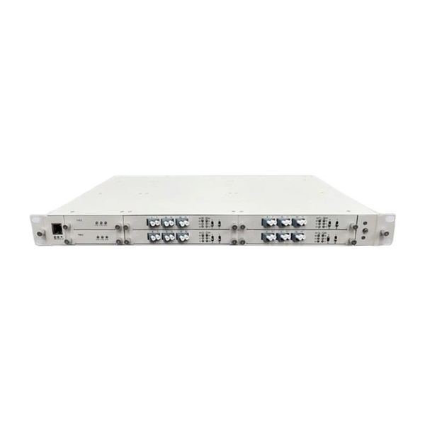
A WDM system uses a at the to join the several signals together and a at the to split them apart. With the right type of fiber, it is possible to have a device that does both simultaneously and can function as an. The optical filtering devices used have conventionally been (stable solid-state single-frequency in the form of.
[PDF]
Normal WDM (sometimes called BWDM) uses the two normal wavelengths 1310 and 1550 nm on one fiber. Coarse WDM provides up to 16 channels across multiple transmission windows of silica fibers. Dense WDM (DWDM) uses the C-Band (1530 nm-1565 nm) transmission window but with denser channel spacing.OverviewIn, wavelength-division multiplexing (WDM) is a technology which a number of signals onto a single by using different (i.e., colors) of. A WDM system uses a at the to join the several signals together and a at the to split them apart. With the right type of fiber, it is possible to have a device that does both s.
[PDF]
It essentially performs some relatively simple time-division multiplexing of lower-rate signals into a higher-rate carrier within the system (a common example is the ability to accept 4 OC-48s and then output a single OC-192 in the 1,550 nm band).OverviewIn, wavelength-division multiplexing (WDM) is a technology which a number of signals onto a single by using different (i.e., colors) of. A WDM system uses a at the to join the several signals together and a at the to split them apart. With the right type of fiber, it is possible to have a device that does both s.
[PDF]
Dense wavelength-division multiplexing (DWDM) refers originally to optical signals multiplexed within the 1550 nm band so as to leverage the capabilities (and cost) of EDFAs, which are effective for wavelengths between approximately 1525–1565 nm (), or 1570–1610 nm (). EDFAs were originally developed to replace optical-electrical-optical (OEO), which they have made pra.
[PDF]
WDM systems are divided into three different wavelength patterns: normal (WDM), coarse (CWDM) and dense (DWDM). Normal WDM (sometimes called BWDM) uses the two normal wavelengths 1310 and 1550 nm on one fiber. Coarse WDM provides up to 16 channels across multiple transmission windows of silica fibers. OverviewIn, wavelength-division multiplexing (WDM) is a technology which a number of signals onto a single by using different (i.e., colors) of. A WDM system uses a at the to join the several signals together and a at the to split them apart. With the right type of fiber, it is possible to have a device that does both s.
[PDF]

This paper will review the development of fiber-optic high-temperature sensors over the last 30 years, presenting their design and fabrication methods according to sensing type and typical temperature measurement performance. The full paper consists of eight sections. Fiber-optic high-temperature sensors are gradually replacing traditional electronic sensors due to their small size, resistance to electromagnetic interference, remote detection, multiplexing, and distributed measurement advantages. This paper reviews the sensing principle, structural design, and. Luna's Optical Backscatter Reflectometer (OBR) products are based on OFDR and provide a level of detail and precision not available with the prevailing fiber optic diagnostic tool - the optical time domain reflectometer (OTDR). OBR systems map out loss along a single-mode fiber (SMF) or multi-mode. breadth and most comprehensive solutions for optical communications test products to be found in one place. Corning's High Temperature Fibers are designed for applications requiring improved fatigue resistance, high usable strength, and excellent resistance to higher temperatures and hydrogen permeation. Thus, wireless communication -situ processing of data would combined with in significantly improve the ability to include sensors into high temperature systems and thus lead toward more intelligent engine systems. NASA Glenn Research Center (GRC) is presently lea, communication systems,ding the.
[PDF]
West Port Middle East specializes in engineering and supplying cable management solutions that meet the precise requirements of electrical contracting projects across the GCC. Unigroup offers a line-up of high-performance cable trays, Trunking and Channel Systems for all your cable routing requirements. Our cable tray systems are engineered for modern infrastructure, ensuring safe, organized, and efficient cable routing across commercial, industrial, and utility. Cable Trays are support systems used in building electrical wiring. These cable support systems are commonly used to support insulated power and communication cables. Cable trays provide a more preferable alternative to electrical conduit systems and open wiring. Cable tray systems are generally. Premium Construction: Made from galvanized steel, stainless steel, or aluminum, these trays resist corrosion and provide high load-bearing capacity in harsh conditions. From residential towers to industrial plants, our extensive portfolio of products and accessories is designed to provide. A form of cable management system used for supporting and arranging electrical cables and wires in commercial, industrial, and residential structures is known as GI Cable Tray, also known as Galvanized Iron Cable Tray.
[PDF]

Telescopic mast system with advanced vibration-dampening technology to minimize jitter and ensure stable communication and data transmission, even in the most demanding terrain and vehicle movements. Fireco designs and manufactures the most comprehensive line of standard and custom telescopic masts using high quality materials with industry leading engineering and quality testing practices to provide our customers with the world's best mobile masts. Will-Burt's telescopic masts and tower systems provide intelligent. Telescopic mast systems play a critical role in modern field operations—enabling elevation of cameras, antennas, lights, sensors, and communication gear in demanding environments. Whether for surveillance, broadcasting, defense, or emergency response, choosing the right mast system ensures reliable. Floatograph, along with its utility industry partner, Eversource Energy, developed the Rapid Pole® – Temporary Power Pole system to reduce customer downtime, allowing crews to re-energize a circuit in as little as 20 minutes. Floatograph's masts come in height options from 10 to 100 feet, and are. Advanced telescopic mast solutions designed for versatility in the field, providing crucial support for on-the-move (OTM) missions. Erecting the Telescoping Mast is made by simply connecting guys and brackets to the attached unique heavy duty rolled edge guy rings and clamps, extend the sections, insert the locking cotter pins, rotating the tubes to.
[PDF]

Managing optical attenuation helps keep your signal safe. Clean your optical connectors so you do not lose. Optical Signal Attenuation is the single greatest factor limiting the distance and performance of your network. Understanding it is crucial for anyone involved in data centers, telecommunications, or enterprise networking. This guide will demystify signal loss, explore its causes, and show you how. In high-speed environments, where the optical link budget is measured in fractions of a decibel, diagnosing and eliminating unexpected loss is the network engineer's most critical task. This field guide provides a systematic, step-by-step approach to troubleshooting and resolving the most common. Signal loss in Fiber Optic networks can make data slow. It can also break your connection. You should fix it fast to get speed and stability back. > You can solve this with simple steps. Signal Degradation (Loss of Light) When the signal quality degrades, it could be a sign of attenuation or excessive loss in the system. The signal might become weaker, resulting in slower speeds or dropped connections. -. Fiber optic networks are celebrated for their speed and reliability, but even the best systems can encounter problems. When issues like signal loss, slow speeds, or intermittent connectivity arise, systematic troubleshooting is key. Things like impurities in the fiber core and reflections at the core-cladding edge cause this drop.
[PDF]
This blog article entry considers the merits of choosing which of various low loss RF coaxial cables to use for IoT, LTE or LORA wireless applications where an external antenna is used to connect to router, gateway or terminal. The choice looks deceptively simple—pick a length, screw it on—but RF engineers know the truth: every extra meter quietly eats away at your link budget, especially once you cross 2 GHz. It's not just about length; the cable type, connector quality, and even mounting environment make a measurable. Audio generated by DropInBlog's Blog Voice AI™ may have slight pronunciation nuances. In this article, we will consider cables such as RG174, RG58, RF195. The cheap connectors have inferior dielectric between the poles as well as poorer grades of metal. The dielectric won't handle high power (KW range) as well and the center pin can more easily shift causing impedance problems if they are moved frequently. RF connectors are usually used with coaxial cables. They are designed to maintain the shielding that the coaxial design offers. The better and newer. Besides the wide range of RF connectors, Telegärtner also provides a considerable range of suitable coaxial low loss cables. Using this one-stop shopping option at Telegärtner makes your purchasing process even more efficient. The main use of low loss cables are all kinds of wireless applications.
[PDF]