Splicing allows you to restore or expand fiber networks while maintaining signal integrity. When done right, splicing ensures minimal loss and long-lasting performance. This is where fiber optic cable splicing—the process of creating a permanent, high-performance join between two fiber ends—becomes critical. For network managers and technicians, a poor splice can lead to significant signal degradation, network downtime, and costly troubleshooting. At Turn-Key. To begin, the standard definition of splicing in optical fiber is joining two fiber optic cables together. The other, more common, method of joining fibers is called termination or connectorization. Splicing is most commonly used in the field but has application in cable assembly houses. Whether repairing a broken cable or extending a fiber run, fiber optic splicing ensures light signals travel. Whether you're installing new cables or repairing damaged ones, splicing techniques play a vital role in maintaining signal integrity. Choosing the right method affects performance, cost, and long-term durability. In this blog, we'll explore the main types of fiber optic splicing techniques, their. Joining two optical fibers at the right place so that light can be transmitted through them with minimal loss and reflection is known as splicing. Fiber optic splicing is done through two main methods. In fusion splicing, the ends of the fibers are welded together with heat. This guide will walk you.
[PDF]

These cables consist of delicate glass tubes layered with polymeric materials. Improper handling can lead to flawed connections and harm to optical components. Protective gear like safety glasses with side shields and gloves should always be worn when working with fiber. Fiber optic cable and copper twisted-pair cable share many similarities. They are both delivered in a coil or on a reel. They are installed in the same general location by the same people for the same general purpose. It is imperative that certain procedures be followed in the handling of these cables to avoid damage and/or limiting their usefulness. A copper wire can take a twist with little worry, but glass. Proper maintenance of fiber optic cables ensures years of reliable performance. Here are some tips you can follow when handling and storing fiber optic cables 1. Keep Cable Connectors Clean and Dry Before using fiber optic cables, clean the connectors on the cable and on the cables or ports the. Safely managing fiber optic cables is crucial to maintain their efficiency and prevent potential damage, despite their considerable tensile strength compared to copper. Here's a detailed breakdown of how to safely manage them: Glass fibers are extremely small and sharp; they can easily penetrate the skin, eyes.
[PDF]
This guide provides a detailed, professional procedure for installing a Residual Current Circuit Breaker (RCCB)—a device essential for protecting people from the severe danger of electric shock. The steps outlined here are fundamental to ensuring the RCCB functions. It is an electrical protective device that protects electrical circuits and devices from some electrical faults such as leakage faults, electrical shock, current unbalance due to equipment failure, etc. It works on the principle of sensing residual current which is why it is called a residual. Distribution board is a safe system designed for house or building that included protective devices, isolator switches, circuit breaker and fuses to connect safely the cables and wires to the sub circuits and final sub circuits including their associated Live (Phase) Neutral and Earth conductors. Residual-current devices, commonly referred to as RCDs, are used in many practical applications. They can be found in fuse boxes, electrical switchgears or industrial machine control systems. Therefore. To wire an RCD fuse box correctly, start by reviewing the diagram to identify each circuit and its corresponding components. Understanding the layout helps prevent mistakes and ensures safe wiring. floor in a multi storey building. The Sub distribution board is connected and supplied from the Main Distribution Board through different wires and cables rated.
[PDF]
In this video, we'll walk you through the process of wiring a home distribution box with a detailed connection diagram. Whether you're an electrician or a DIY enthusiast, this guide will help you understand the basics of home electrical distribution. more Welcome to our channel! In this video. An electrical panel box, also known as a breaker box or a distribution board, is a crucial component of any electrical system. It serves as a central hub for distributing electricity throughout a building, ensuring that power is delivered safely and efficiently to all the required locations. What is Distribution Board? Distribution board. Hey, in this article we are going to see the Single Phase Distribution Box Wiring Diagram and Connection Procedure. And all the switching and protective devices are installed in the. Are you ready to master the skill of building electrical panels? This detailed guide provides an excellent base for beginners. Learn about the essential components of panels, such as the circuit breakers and fuses that safeguard against hazards. Then, delve into complex wiring configurations. Single Phase wiring installation is the most common wiring in residential buildings. In Single Phase supply (230V in UK, EU and 120V & 240V in the US & Canada), there are two (one is Line (aka Phase, Hot or Live) and the other one is Neutral) incoming cables from the utility poles to the kWh energy.
[PDF]
Flex electrical cable, often referred to as flexible cable or flex, is a type of wire that is designed to withstand repetitive bending and movement without damage. Article 400 covers the general requirements and applications for flexible cords as contained in Table 400. A “flexible cord” is two or more insulated conductors enclosed in a flexible covering. Figure 01 The NEC does not. What is a flexible cable? Flexible cables are cables that have multiple conductors (Class 5 or Class 6 conductors) that form the conductor and are insulated and sheathed in a lightweight, flexible material (usually plastic or rubber). Why choose flexible cables for domestic use? It is suitable for. These include flat flexible cable (FFC), stranded wire, power cables, control cables, and flexible electrical conduit. Each type meets specific needs across industries like automotive, electronics, and medical devices. Here is a quick look at how leading cable types are used worldwide: You can. Power distribution cables present a unique challenge to electrical wire interconnect system engineers. Unlike rigid electrical wiring, which is designed for static installations within buildings, walls, or. In any electrical system—whether powering lights in homes, machinery in factories, or robots in operation—cables are the unsung heroes, safely and reliably transmitting electrical energy. As the backbone of power distribution systems, cables connect power sources (such as circuit breakers) to.
[PDF]

Run a ground wire from your metal patch panel rack to the grounding bar, use grounding lugs on the rack. Probably not necessary, but use Noalox between the lug and the rack. Remove paint if you want to go all in. Install and ground coax grounding blocks for your antenna. A Cat6 shielded patch panel is a modular component that connects and organizes multiple Ethernet cables in a central location. Unlike unshielded panels, shielded patch panels feature a conductive metal body and a grounding terminal to block EMI and maintain network integrity. GYA's shielded patch. A patch panel is a hardware device used to organize and manage network cable connections, helping to keep network wiring neat and efficient. Based on the shielding type, Cat6 copper patch panels are categorized into two types: shielded and unshielded. The rack itself is then bonded to the Secondary Busbar (SBB) of the telecommunications room. This. Correct STP grounding turns shielding into real EMI protection. This guide shows how to maintain drain‑wire continuity, bond safely at the equipment side, avoid ground loops, and validate results with simple tests. Cabling is cat5e UTP for data and phone. Coax is RG6 with 2 seperate runs, one for commercial tv provider, other for an attic mounted antenna that I'd like to eventually move to the roof. Is there a requirement (USA NEC) to.
[PDF]

This video shows real on-site footage of electrical installation, demonstrating safe and standardized wiring methods used by professionals. more Learn how to wire a distribution box step by step!. Plastic is lighter and good for indoor setups. Choose based on where you'll install the box. Inside the box, you'll find things like circuit breakers, busbars, terminal blocks, and wires. These parts control and distribute the electricity to different circuits safely. Some boxes also include DIN. Strictly speaking, the word “Distribution Box (D-box)” can refer to two categories: electrical distribution boxes and septic tank distribution boxes. This article mainly talks about the first one. I'll cover these four popular conduits: Remember, electrical conduits can be either rigid or flexible, and they come in various materials like metal, aluminum. NEC Article 314 establishes requirements for the installation and use of electrical boxes, conduit bodies, fittings, and handhole enclosures. A conduit body is a removable-cover section of a conduit system that provides access at junctions or termination points. Article 314 applies to: These. Where metal boxes or conduit bodies are installed with messenger-supported wiring, open wiring on insulators, or concealed knob-and-tube wiring, conductors shall enter through insulating bushings or, in dry locations, through flexible tubing extending from the last insulating support to not less.
[PDF]
This video shows real on-site footage of electrical installation, demonstrating safe and standardized wiring methods used by professionals. Covers wiring, placement, standards, and expert tips for a compliant setup. A distribution box is the heart of any electrical system. It takes the incoming power and safely distributes it to different circuits throughout your building. In this video, we'll walk you through the process of wiring a home distribution box with a detailed connection diagram. Whether you're an electrician or a DIY enthusiast, this guide will help you understand the basics of home electrical distribution. It has three categories: residential, commercial and industrial electrical distribution boxes, all of which play important roles in their respective electrical. This guide aims to provide a comprehensive overview of double wide mobile home electrical wiring diagrams, covering everything from the main service panel to individual circuits. This panel is. Box installation: Make sure that Distribution box has been correctly installed and fixed. Material preparation: Prepare the required circuit breakers, wires, wiring ties and other materials, and ensure that they meet the design drawings and installation requirements. Location determination:.
[PDF]

In this video, you will learn: The essential components of a distribution board, including MCBs (Miniature Circuit Breakers), RCDs (Residual Current Devices), and busbars. How to safely connect incoming and outgoing cables to the DB box. The importance of earthing and. A distribution box is the heart of any electrical system. It takes the incoming power and safely distributes it to different circuits throughout your building. Whether in a home or an industrial facility, this box keeps your electrical setup organized, functional, and efficient. The distinction between 1P and 2P circuit breakers plays a pivotal role in determining the appropriate protection level for various circuits. In case of high power use, to meet the demand of currentAnd in order for the current to be carried at the demanded high powers to be met, the method of parallel connection of the cables can be selected. And when this method is selected, multiple cables need to be used for each phase. In the event. Welcome to our channel @Electricalgenius In this video, we'll take you through a detailed step-by-step guide on wiring a home distribution DB (Distribution Board) box. And all the switching and protective devices are installed in the distribution box. Single Phase Distribution Box generally consists of Double Pole MCBs, Single Pole MCBs, and RCCBs.
[PDF]

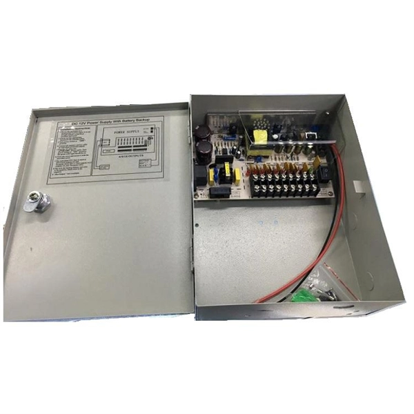
In this video, we'll walk you through the process of wiring a home distribution box with a detailed connection diagram. Whether you're an electrician or a DIY enthusiast, this guide will help you understand the basics of home electrical distribution. more Welcome to our. Material preparation: Prepare the required circuit breakers, wires, wiring ties and other materials, and ensure that they meet the design drawings and installation requirements. Location determination: Determine the installation position of the circuit breaker according to the position of the. An electrical panel box, also known as a breaker box or a distribution board, is a crucial component of any electrical system. It serves as a central hub for distributing electricity throughout a building, ensuring that power is delivered safely and efficiently to all the required locations. What is Distribution Board? Distribution board. A distribution board (also known as a service panel or breaker box) is a centralized collection of circuit breakers, fuses, and/or relays used to control and protect the wiring in a home. The diagram of the distribution board's wiring shows exactly how each circuit is wired and connected.
[PDF]
In this video, we'll walk you through the process of wiring a home distribution box with a detailed connection diagram. Whether you're an electrician or a DIY enthusiast, this guide will help you understand the basics of home electrical distribution. more Welcome to our channel! In this video. An electrical panel box, also known as a breaker box or a distribution board, is a crucial component of any electrical system. It serves as a central hub for distributing electricity throughout a building, ensuring that power is delivered safely and efficiently to all the required locations. Distribution Board or DB is an electricity supply system or a common enclosure that distributes the electrical power feed into subcircuits. It includes isolator, RCCB (Residual current circuit breaker) or RCD (Residual-current device) devices, protective fuses or MCB's (Miniature Circuit Breaker). Learn how to install a distribution box safely and correctly. Covers wiring, placement, standards, and expert tips for a compliant setup. It takes the incoming power and safely distributes it to different circuits throughout your building. Box installation: Make sure that Distribution box has been correctly installed and fixed. Material preparation: Prepare the required circuit breakers, wires, wiring ties and other materials, and ensure that they meet the design drawings and installation requirements. To understand how a breaker box works, it is helpful to.
[PDF]

A mesh network wifi router (with satellites) is the best way to cover your home while overcoming signal degradation because of the walls and floors. Assuming your ISP is cable, wire a receptacle in a closet and pull the cable into the same closet. Plug in the main router there. A fiber-optic connection is the best choice for fast home internet as it has a number of advantages compared to traditional copper cables, such as faster speeds and less interference. Many major ISPs, such as Verizon and Xfinity, offer fiber connections directly to your door, known as FttP or Fiber. But if you want to get the full potential of this internet, invest in a Wi-Fi router that handles its speed and reliability. Put the satellite. Provides a nearly invisible fiber path to directly connect your modem to a computer, TV, or gaming console — no drywall repairs, no tripping hazards, no complaints from your spouse. Two Ethernet to fiber converters are included which allows connection to any devices with Ethernet ports. NEMA 1-15. However, you need a router capable of supporting multi-gig speeds to get fiber internet connectivity. With the many options available on the market, picking the best router for fiber internet can be tricky. Our top overall pick is the Netgear Nighthawk RS700S, a Wi-Fi 7 router built for multi-gig fiber plans that handles up to 200 devices across 3,500 square feet. For budget-conscious.
[PDF]
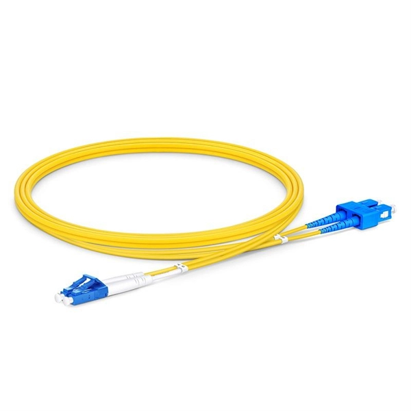
You use optical couplers and splitters to split or join signals in fiber networks. These devices help you control light signals well. For example, optical splitters send light to many output ports. A fiber optic splitter is a passive optical component that divides a single incoming optical signal into two or more outgoing signals, or combines multiple incoming signals into one. Unlike active devices (which require power), splitters operate without electricity, relying solely on the physics of. Fiber optic cables consist of thin strands of glass or plastic fibers that transmit data as light signals. Each fiber is composed of a core, cladding, and a protective outer coating. The core is where light travels, while the cladding reflects light back into the core to minimize signal loss. The. Fiber optics, a cornerstone of modern telecommunications, relies on transmitting data through light signals within fiber optic cables. You can also use them to join light from. A fiber broadband provider typically determines and overall split ratio for the network, such as 1x32 or 1x64, and uses combinations of splitters to meet that ratio with each PON port. 1x32 splits were common in North America for G-PON architectures. These fibers transmit data as light signals, which are converted into electrical signals at the receiving end. The benefits of optical cables are numerous.
[PDF]