The Lightning Pick system is so intuitive and easy to understand that temporary workers can be effective with just a few minutes of training. Complex systems with steep training curves don't fit modern warehousing and order picking n. The Lightning Pick system is so intuitive and easy to understand that temporary workers can be effective with just a few minutes of training. Complex systems with steep training curves don't fit modern warehousing and order picking needs. Also, these systems are highly adaptable, so they evolve along with your business. Light modules are easy to ad. When an SKU must be picked from a specific location, the right indicator turns on to indicate action is required. The picker selects the quantity displayed and confirms the pick by pressing the lighted button. Light-directed picking systems can easily be configured to drive performance make picking more efficient for: 1. Fast, medium and slow velocity SKUs 2. Order picking, kitting and sortation 3. Full and split-case picking 4. Many popular picking methodologies such as zone picking, cluster picking, bucket brigade, batch picking, order consolidation, s.
[PDF]

If the LOS light on your fiber router or ONT is blinking red, it usually means Loss Of Signal. This guide explains the likely causes, the checks you can do at home, and when the issue needs technician support. The LOS light on your router indicates the status of your internet connection to the Internet Service Provider (ISP). When it's green and steady, everything is fine. However, when it blinks red or stays solid red, it signifies a Loss of Signal, a problem preventing your router from communicating. Troubleshoot your router's red light with these steps. You might feel like you're staring into the abyss of digital darkness, wondering what went wrong. But don't despair! This guide will walk you through the most common causes of router. The tables in this article provide detailed information about the possible appearances of the LED lights on each device, the possible causes of each state, and what you should do. Existing Krishii Fiber customers can share their registered mobile number, area and a. Experiencing a solid red broadband light on your router can be frustrating and indicates a disruption in your internet connection. Understanding the possible causes and fixes for this issue is crucial to getting your connection back on track. We will explore common reasons behind the solid red.
[PDF]

When it comes to testing fiber optic cables, a Visual Fault Locator (VFL) is an essential tool in your toolkit. A VFL is used to detect faults, breaks, or bends in fiber optic cables by emitting a bright red light that is visible even through the fiber's jacket. It's a cost-effective and. A Visual Fault Locator which can be also called visual fault identifier (VFI), fiber fault locator, fiber fault detector, etc., is a visible red laser light designed to inject visible red light energy into an optical fiber. Using a VFL to diagnose issues can save time and cost when diagnosing an. A visual fault locator is a compact, handheld device that emits a visible light beam, typically in the red wavelength range, through a fiber optic cable. It works by injecting a visible red laser light into the fiber, which can be seen through the jacket or at the end of the cable. If the light doesn't come out the other side, there might be a problem. You. And in the end we will show you how to use an old cell phone's camera to detect light in a fiber optic system. It uses a bright incandescent bulb or visible LED source to.
[PDF]

Insertion loss tells you how much weaker the signal becomes after passing through the splitter. Let's say you have a laser output at 0 dBm (which is 1 milliwatt of optical power). If you use a 1×8 splitter with ~10. 5 dB of insertion loss, the power at each output would be: 0 dBm – 10. 5. Enter excess loss from the splitter datasheet for your wavelength. Add connector and splice quantities with realistic planning losses. Include any additional component losses and an engineering margin. Enable power budget to estimate received power and margin. Press Calculate to show results above. Understanding optical splitter loss isn't just about plugging numbers into a calculator. It's about knowing what factors contribute to that loss, how manufacturers specify it, and how it impacts the overall performance and reach of your network. Ignore it, and you might find your signal too weak to. Optical insertion loss refers to the signal loss resulting from the insertion of components such as connectors or splices in an optical fiber system. Common ratios: For cascades, add losses and validate margin using the Optical Budget tool. This Fiber Optic Splitter Insertion Loss is the splitter devices loss, Considering fiber connectors or connectors+adapter insertion loss in LGX, The fiber splitter IL would be a little bigger. To make clear the basic ftth fiber splitter loss in performance, You can refer to the below loss chart.
[PDF]

This paper presents a method for the CTE measurement of composite specimens using Fiber Bragg Grating (FBG) sensors. FBG sensors consist of periodic refractive index variation made on the core of optical fiber. When a broadband source is given to the FBG, one. Coefficient of Thermal Expansion is defined as where dl is the change in length for the temperature change dT and l is the original length. There are various conventional measurement techniques for the determination of the CTE, namely dilatometry , interferometry and thermomechanical. Measurement of the Coefficient of Thermal Expansion of Materials Access to the requested content is limited to institutions that have purchased or subscribe to SPIE eBooks. You are receiving this notice because your organization may not have SPIE eBooks access. Pure thermoplastic and composite specimens were built using different commercially available filament. A variation of the period of the grating inscripted in a fiber optic – induced by mechanical or thermal perturbation – causes a shift of the reflected peak wavelength, due to the related optical path length variation. where Pij are the Pockel coefficients of the elasto-optic tensor, n is the.
[PDF]
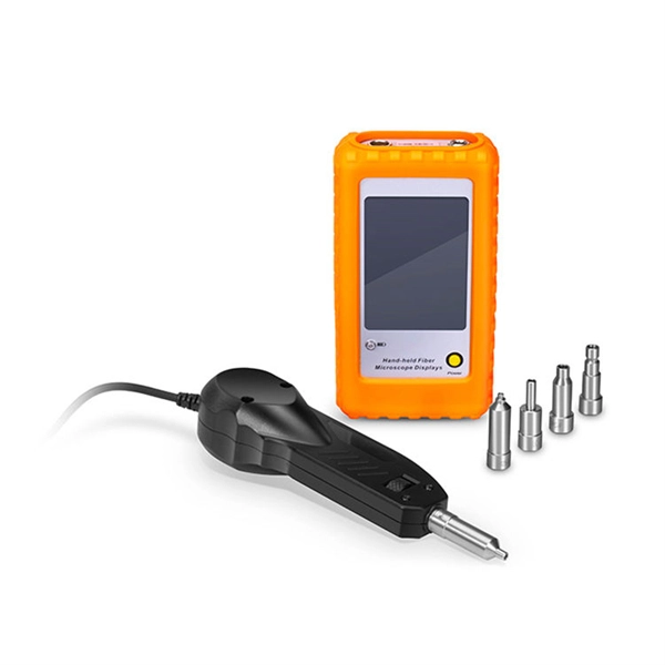
An optical power meter (OPM) is a device used to measure the power in an signal. The term usually refers to a device for testing average power in systems. Other general purpose light power measuring devices are usually called,, power meters (can be sensors or ), or lux meters. A typical optical power meter consists of a , measuring and display. The sens.
[PDF]

A relay protection tester is a core device used to verify the performance of relay protection devices. Its working principle can be summarized as “signal excitation – behavior detection. ”. It is divided into two parts: the main loop and the auxiliary loop. ” The tester has a built-in high-precision programmable power supply, capable of simulating various operating. When the transformer wiring type is Y/Y (Y0), the test wiring is very simple: when testing phase A, the tester IA is connected to the phase A of the high voltage side, and the tester IB is connected to the phase a of the low voltage side. After the neutral line of the high and low voltage sides is. Relay protection aids in detecting and preventing faults in electrical systems such as overcurrents or short circuits. As a core part of electric system reliability and safety, protective relays aid in preserving equipment and maintaining stability by isolating affected zones automatically via. THEY SHOULD BE GIVEN FIRST LINE MAINTENANCE ATTENTION. COMPREHENSIVE INSPECTION, MAINTENANCE AND TESTING PROGRAM. ” relay may only need to operate for 0. 15 seconds in its 30+ year life. But failure to operate as intended can result in extensive damage, extended power outages, and loss of life. NETA. Megger's smart relay testing solutions and expert support help you validate protection performance, improve system reliability, and ensure continuity of power across your network.
[PDF]

If the LOS light on your fiber router or ONT is blinking red, it usually means Loss Of Signal. This guide explains the likely causes, the checks you can do at home, and when the issue needs technician support. This guide will walk you through what the LOS light means, why it blinks red and step-by-step instructions on how to resolve the issue, including resetting your router. What Does the LOS Light Indicate? The LOS light on your router indicates the status of your internet connection to the Internet. Troubleshoot your router's red light with these steps. A red light on your router can be a source of frustration and confusion. Fortunately, diagnosing and resolving these issues doesn't have to be. A router showing a red light can mean different things, like a service outage, misconfiguration, or loose connection, all of which can lead to a broken internet connection. Fortunately, there are heaps of ways to fix a red blinking light on your router. One of the first things you should try is to. That blinking red LOS light means your router has lost its connection to your internet provider's network. Before you panic or call tech support, there are several simple fixes you can try at home that often solve this problem in minutes. You might feel like you're staring into the abyss of digital darkness, wondering what went wrong.
[PDF]
A blinking red light on a ZTE WiFi 6 router typically indicates that the router is powered on but isn't receiving an internet signal from the fiber line, or the connection hasn't been fully activated by the provider. First, check the physical connection between the. This guide will walk you through what the LOS light means, why it blinks red and step-by-step instructions on how to resolve the issue, including resetting your router. NSI-79750LW Round Indicator Light with Non Replacable Lamps, Press Fit, 0. 5" Panel Cutout, 0. uxcell 2Pcs Red Green Indicator Light. That blinking red LOS light means your router has lost its connection to your internet provider's network. Before you panic or call tech support, there are several simple fixes you can try at home that often solve this problem in minutes. The LOS light on your router stands for “Loss of Signal. Understanding the possible causes and fixes for this issue is crucial to getting your connection back on track. We will explore common reasons behind the solid red.
[PDF]
Fibre-optic Link Around the Globe (FLAG) is a 28000km (17,000miles) fibre optic mostly- submarine communications cable that connects the United Kingdom, Japan, India, and many places in between. The cable is operated by Global Cloud Xchange, a subsidiary of RCOM. These cables stretch thousands of kilometres beneath the sea, carrying the digital world across continents. New Delhi: Internet is an inseparable part of life in this modern world. Social media. These undersea cables carry almost all international data, connecting continents and countries. They're like the invisible highways of our digital world. Today, tech giants like Google, Facebook, Amazon, and Microsoft own or lease more than half of the undersea bandwidth. The world depends on digital links and the control of these cables decides how information moves between. Private telecom and technology companies own and operate nearly all submarine internet cables, which carry 99% of global internet traffic. These companies invest heavily in laying and maintaining the vast network of fiber-optic cables that connect continents and enable international data flow. The system runs from the.
[PDF]
Fiber-optic communication is a form of optical communication for transmitting information from one place to another by sending pulses of infrared or visible light through an optical fiber. The light is a form of carrier wave that is modulated to carry information. Fiber is preferred. This method encodes data into light signals by modulating properties like wavelength, phase, and polarization. The light signals propagate to the receiver through the fiber optic cable. Optical fiber communication relies on the properties of light from the electromagnetic spectrum. By optimizing. These strands, known as fibre optic cables, have revolutionised telecommunications because they transmit information using pulses of light. Unlike copper wires, which send electrical signals and suffer from resistance and interference, fibre optics offer orders of magnitude more bandwidth and. Optical Fiber Light Transmission commonly known as fiber optics is a technology that utilizes thin transparent fibers made of glass or plastic to transmit data and information using the light signals. This technology forms the backbone of global data transfer due to the immense bandwidth capacity of light. Light waves possess a frequency spectrum vastly wider than. Less costly per meter. Lower transmitter launching power. Less susceptible to electromagnetic interference. Flexible use in mechanical and medical imaging systems. Automotive and many other industories.
[PDF]

When it comes to testing fiber optic cables, a Visual Fault Locator (VFL) is an essential tool in your toolkit. A VFL is used to detect faults, breaks, or bends in fiber optic cables by emitting a bright red light that is visible even through the fiber's jacket. Let's dive into everything you need to know about mastering VFLs. It's a cost-effective and. Visual Fault Locator (VFL) testing is one of the most fundamental inspection methods used in FTTH, ODN, and data center environments. A VFL emits a visible red laser (typically 650 nm) that travels along the fiber core and leaks out at points of excessive loss, fiber breaks, or microbends. Although. The Fiber Visual Fault Locator Kit is an essential tool for network technicians and engineers; it provides an accurate and quick method of finding such problems as breaks, bends or faults that may affect the network's operation. It works by injecting a visible red laser light (usually in the 650nm wavelength) into the fiber. When the light encounters a fault, such as a break, bend, or bad splice, it leaks out of the fiber, making the. Conducting efficient, repeatable fiber optic cable certification requires an array of specialized test equipment: Optical Loss Test Set (OLTS) – Integrates adjustable light source and power meter for efficient, Tier-1 insertion loss testing. Visual Fault Locators – Handheld devices projecting.
[PDF]

Shines green when PoE is being drawn (active PoE). Shines blue when link speed is 10 Gbps (max port speed). Turned off when device is online. The PSX28 is equipped with several LED indicators to display the device's operational status and activity. The number of PoE devices that they can run depend on the model, how much current each device requires, and on the power supply used for the POEmax. The 100 Watt (W) model supplies enough power for seven devices to draw the maximum load (13W each). The 50W models run four or seven devices in any. The lights on POE switches mainly include power indicator lights, system operation status lights, POE mode status lights, and business interface indicator lights. Their meanings are as follows: Power indicator light (PWR): Green constantly on: indicates that the power supply of the switch is normal. POEmax S witch Assembly (8 RJ-45 Ethernet Ports w/ 1 PoE Input, 8 Link-Activity LED' s, 1 Po wer LED, P ower Input Jack, 2 Slide R ails w/Rubber F eet). 5Amp); IPS8450/8750 Models: 50W (1Amp); IPS8000/8400 Models: None, PoE. Perhaps it crashed before it could finish displaying it. Example of the complete display here:.
[PDF]