Light sources are devices that generate the optical signals transmitted through fiber optic cables. In fiber communication, the most commonly used light sources are LEDs (Light Emitting Diodes) and laser diodes. LEDs are used in short-distance, low-speed systems due to their broader spectral width. Optical fiber primarily uses infrared light, not visible light, due to lower signal attenuation. Common wavelengths are 1310nm and 1550nm, where silica glass fiber has minimal loss (as low as 0. Lasers or LEDs generate the light, which carries data through total internal reflection within. Most systems use a "transceiver" which includes both transmission and receiver in a single module. The transmitter takes an electrical input and converts it to an optical output from a laser diode or LED. It often uses glass or plastic cables, which address the problems of traditional copper cables' poor speed and limited distance bandwidth carrying. VCSEL (Vertical Cavity Surface Emitting Laser)- VCSELs (pronounced 'vixel') emerged in the 80's as a new kind of semi-conductor laser and were soon recognized for their potential in fiber optics. When Gigabit Ethernet products were developed LEDs could not modulate (turn on and off) at required.
[PDF]

A laser diode is a semiconductor device that emits light when an electric current is passed through it. The light emitted by it is very intense and narrowly focused, making it an ideal source of light for use in optical fiber communications and laser printers. In this article, we will discuss the. The optical power value, Po, is the most basic characteristic of a laser diode. This parameter is defined as the light output intensity in the case that a specific current is applied to the device in the forward direction, and is typically expressed in units of W. It operates similarly to a light-emitting diode (LED) but produces a focused, monochromatic, and coherent beam of light. These gadgets track down wide applications because of their proficiency and minimal size. When electric current flows through the p-n junction, the gain is. A Laser Diode is a semiconductor device similar to a light-emitting diode (LED). It uses p-n junction to emit coherent light in which all the waves are at the same frequency and phase. They consist of a p-n semiconductor junction, with a forward bias voltage applied.
[PDF]

A lighting control module operates as the central controller for a lighting system. It receives input from switches, apps, or sensors and regulates electrical flow to connected lights. Depending on the setup, it adjusts brightness, color temperature, or full lighting scenes. It acts as a bridge between your physical lighting fixtures and the smart systems that manage them. Instead of relying solely on traditional wall switches, you can control your lights via remotes, mobile or web apps. A lighting control module is an essential component in a lighting control system that manages how lights are powered, dimmed, or switched on and off. Think of it as the “brain” that receives commands—either from a manual switch, a sensor, or a building automation system—and translates them into. A lighting control module is a smart device that manages lighting circuits, adjusting brightness, automating schedules, and responding to sensors. It enhances comfort, efficiency, and ambience in homes and commercial spaces. Explore the multifaceted benefits and applications of lighting control modules, from home automation to industrial. These modules are designed to communicate with various sensors, switches, and control panels, making lighting adaptable to different environments and user preferences. It enables precise management of lighting systems, allowing for adjustments in brightness, color, timing, and even integration with other smart devices. This innovation.
[PDF]

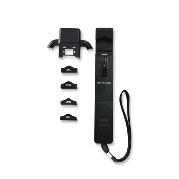
When it comes to testing fiber optic cables, a Visual Fault Locator (VFL) is an essential tool in your toolkit. A VFL is used to detect faults, breaks, or bends in fiber optic cables by emitting a bright red light that is visible even through the fiber's jacket. It's a cost-effective and. A Visual Fault Locator which can be also called visual fault identifier (VFI), fiber fault locator, fiber fault detector, etc., is a visible red laser light designed to inject visible red light energy into an optical fiber. Using a VFL to diagnose issues can save time and cost when diagnosing an. A visual fault locator is a compact, handheld device that emits a visible light beam, typically in the red wavelength range, through a fiber optic cable. It works by injecting a visible red laser light into the fiber, which can be seen through the jacket or at the end of the cable. If the light doesn't come out the other side, there might be a problem. You. And in the end we will show you how to use an old cell phone's camera to detect light in a fiber optic system. It uses a bright incandescent bulb or visible LED source to.
[PDF]

It operates by emitting a bright and visible red laser light into the fiber and detecting the location of faults by observing the light leaking out of the fiber. It is also possible to locate faults in OTDR dead zones and perform fiber identification from one end to the other. When it comes to testing fiber optic cables, a Visual Fault Locator (VFL) is an essential tool in your toolkit. It's a cost-effective and. Whether you're a seasoned technician or a fiber enthusiast, a VFL is the first step to make your life easier in troubleshooting a fiber optic cabling issue. We will be explaining what The VFL's primary purpose is, and how best to use it. Below are some key use cases for a VFL. It gives instant visual proof of where light escapes the fiber. Even beginners can spot bends, cracks, or bad splices without complex tools. A visual fault locator saves time, cuts stress, and reduces repeat work., optical fiber fault detector, optical fiber fault test pen) is a 650nm (± 20nm) semiconductor laser as a light-emitting device, which emits stable red light through a constant current source drive, and connects with the optical interface into the optical fiber, so. In the world of fiber optic communication, diagnosing and troubleshooting network issues is essential to maintain smooth connectivity. Whether you are a beginner or a professional working with fiber optics.
[PDF]
Time domain reflectometers are commonly used for in-place testing of very long cable runs, where it is impractical to dig up or remove what may be a kilometers-long cable. They are indispensable for preventive maintenance of telecommunication lines, as TDRs can detect resistance on joints and connectors as they corrode, and increasing insulation leakage as it degrades and absorbs. OverviewA time-domain reflectometer (TDR) is an electronic instrument used to determine the characteristics of by observing. It can be used to characterize and locate faults in metallic cables (for. A TDR measures reflections along a conductor. In order to measure those reflections, the TDR will transmit an incident signal onto the conductor and listen for its. If the conductor is of a uniform.
[PDF]

Insertion loss tells you how much weaker the signal becomes after passing through the splitter. Let's say you have a laser output at 0 dBm (which is 1 milliwatt of optical power). If you use a 1×8 splitter with ~10. 5 dB of insertion loss, the power at each output would be: 0 dBm – 10. 5. Enter excess loss from the splitter datasheet for your wavelength. Add connector and splice quantities with realistic planning losses. Include any additional component losses and an engineering margin. Enable power budget to estimate received power and margin. Press Calculate to show results above. Understanding optical splitter loss isn't just about plugging numbers into a calculator. It's about knowing what factors contribute to that loss, how manufacturers specify it, and how it impacts the overall performance and reach of your network. Ignore it, and you might find your signal too weak to. Optical insertion loss refers to the signal loss resulting from the insertion of components such as connectors or splices in an optical fiber system. Common ratios: For cascades, add losses and validate margin using the Optical Budget tool. This Fiber Optic Splitter Insertion Loss is the splitter devices loss, Considering fiber connectors or connectors+adapter insertion loss in LGX, The fiber splitter IL would be a little bigger. To make clear the basic ftth fiber splitter loss in performance, You can refer to the below loss chart.
[PDF]

The basic design of an optocoupler consists of a light source, usually an LED (Light-Emitting Diode), driven by the input signal which could be a digital or analogue voltage/current depending upon the characteristics of the light source. An optocoupler (or opto-isolator) is a component that transfer signals between circuits using light. In this guide, you'll learn how they work and how you can use one in your own projects. Optocouplers are very useful when you need to isolate different sections of a circuit, for example in power. Optocouplers, also known as opto-isolators, uses infrared light to transfer electrical signals between two electrically isolated circuits and are commonly classified by their photosensitive output device What is an Optocoupler? An optocoupler (also called an opto-isolator, photo-coupler, or optical. An optocoupler is a tiny part that moves signals between circuits without letting electricity jump across. It uses light to do the job, which helps keep things safe. That way, noisy signals, voltage spikes, or weird grounding issues don't mess with sensitive electronics. Opto-isolators prevent high voltages from affecting the system receiving the signal. We will explore the basics of optocoupler selection and their functionality, helping.
[PDF]

The transmissive liquid crystal spatial light modulator is composed of an active matrix type liquid crystal board of a thin film transistor (TFT) and its accompanying driving circuit. The LCD board is also integrated with some driving circuits, making the driving method more stable. Spatial light modulator (SLM) is a kind of device that can load information on one-dimensional or two-dimensional optical data field, so as to effectively use the proper velocity, parallelism and interconnection ability of light. It is widely used in the field of modern optical information processing. According to the. The LC 2012 is our basic Spatial Light Modulator system based on a translucent liquid crystal microdisplay with a resolution of 1024 x 768 pixel (XGA). The device is mainly intended for proof of concepts and education. Here, we report on the design and realization of an optically addressable. Spatial light modulators, as dynamic flat-panel optical devices, have witnessed rapid development over the past two decades, concomitant with the advancements in micro- and opto-electronic integration technology. The SLMs are available as single mask configuration for phase or amplitude/polarization modulation.
[PDF]

When it comes to testing fiber optic cables, a Visual Fault Locator (VFL) is an essential tool in your toolkit. A VFL is used to detect faults, breaks, or bends in fiber optic cables by emitting a bright red light that is visible even through the fiber's jacket. Let's dive into everything you need to know about mastering VFLs. It's a cost-effective and. Visual Fault Locator (VFL) testing is one of the most fundamental inspection methods used in FTTH, ODN, and data center environments. A VFL emits a visible red laser (typically 650 nm) that travels along the fiber core and leaks out at points of excessive loss, fiber breaks, or microbends. Although. The Fiber Visual Fault Locator Kit is an essential tool for network technicians and engineers; it provides an accurate and quick method of finding such problems as breaks, bends or faults that may affect the network's operation. It works by injecting a visible red laser light (usually in the 650nm wavelength) into the fiber. When the light encounters a fault, such as a break, bend, or bad splice, it leaks out of the fiber, making the. Conducting efficient, repeatable fiber optic cable certification requires an array of specialized test equipment: Optical Loss Test Set (OLTS) – Integrates adjustable light source and power meter for efficient, Tier-1 insertion loss testing. Visual Fault Locators – Handheld devices projecting.
[PDF]
Cable tray support quantity can be calculated using a simple formula: Support Quantity = Total Length ÷ Support Spacing + 1 20 ÷ 2 + 1 = 11 supports In a typical project, a 20-meter cable tray with 2-meter spacing requires 11 supports. This article explains the principles, methods, and practical examples for calculating cable tray support quantity. Ensure NEC compliance, estimate wire length/weight, calculate deflection, and generate hardware BOMs for bends, tees, and reducers. Ideal for electrical contractors and engineers. The. This guide provides a comprehensive approach to calculating cable tray loads, considering various factors such as cable weight, tray weight, environmental influences, and safety factors. Classification of Loads Cable tray loads can be classified into the following categories: Dead Load (G): This. This page also guides to determine the appropriate distance between supports for the load, based on number of cables, cable tray size, and bracket type. Wire Mesh Cable Tray Fill Ratio = Cross section of cable / Cross section of tray According to NEC 392. 9 (B), when using ventilated tray with multi. The National Electrical Code (NEC) covers many aspects of cable tray supports and fittings. The National Electrical Code is a set of principles designed to promote public safety and welfare, as well as safeguard public health by regulating the design and operation of electrical facilities and.
[PDF]

If the LOS light on your fiber router or ONT is blinking red, it usually means Loss Of Signal. This guide explains the likely causes, the checks you can do at home, and when the issue needs technician support. This guide will walk you through what the LOS light means, why it blinks red and step-by-step instructions on how to resolve the issue, including resetting your router. What Does the LOS Light Indicate? The LOS light on your router indicates the status of your internet connection to the Internet. Troubleshoot your router's red light with these steps. A red light on your router can be a source of frustration and confusion. Fortunately, diagnosing and resolving these issues doesn't have to be. A router showing a red light can mean different things, like a service outage, misconfiguration, or loose connection, all of which can lead to a broken internet connection. Fortunately, there are heaps of ways to fix a red blinking light on your router. One of the first things you should try is to. That blinking red LOS light means your router has lost its connection to your internet provider's network. Before you panic or call tech support, there are several simple fixes you can try at home that often solve this problem in minutes. You might feel like you're staring into the abyss of digital darkness, wondering what went wrong.
[PDF]

FTTP ONT red light often indicates optical signal loss or fiber cable connection issues. First, check the fiber optic cable for bends, damage, or loose connections at the. An optical audio cable should have a red light at each of the connectors when it's in place and working correctly. If you don't see the light at either of the ends, the cable isn't connected properly, is broken, or you might just have a faulty cable. The light is an indicator of a problem, rather. Customer: The power light is green, the optical light is red, and the UNI-D 1 port is orange. Credit: Jim Gensheimer for Stanford University Light does a lot of work in the modern world, enabling all types of information technology, from TVs to satellites to fiber-optic cables that carry. An optical amplifier is a device which receives some input signal light and generates an output signal with higher optical power. Typically, inputs and outputs are laser beams (very rarely other types of light beams), either propagating as Gaussian beams in free space or in a fiber. The. An optical amplifier is a device that amplifies an optical signal directly, without the need to first convert it to an electrical signal. I'm just wondering because I had a fiber optic cable plugged in and pulled it out while using it and just hoping that didn't cause some issue. Most optical outs are.
[PDF]
