
Telescopic mast system with advanced vibration-dampening technology to minimize jitter and ensure stable communication and data transmission, even in the most demanding terrain and vehicle movements. Fireco designs and manufactures the most comprehensive line of standard and custom telescopic masts using high quality materials with industry leading engineering and quality testing practices to provide our customers with the world's best mobile masts. Will-Burt's telescopic masts and tower systems provide intelligent. Telescopic mast systems play a critical role in modern field operations—enabling elevation of cameras, antennas, lights, sensors, and communication gear in demanding environments. Whether for surveillance, broadcasting, defense, or emergency response, choosing the right mast system ensures reliable. Floatograph, along with its utility industry partner, Eversource Energy, developed the Rapid Pole® – Temporary Power Pole system to reduce customer downtime, allowing crews to re-energize a circuit in as little as 20 minutes. Floatograph's masts come in height options from 10 to 100 feet, and are. Advanced telescopic mast solutions designed for versatility in the field, providing crucial support for on-the-move (OTM) missions. Erecting the Telescoping Mast is made by simply connecting guys and brackets to the attached unique heavy duty rolled edge guy rings and clamps, extend the sections, insert the locking cotter pins, rotating the tubes to.
[PDF]

This paper will review the development of fiber-optic high-temperature sensors over the last 30 years, presenting their design and fabrication methods according to sensing type and typical temperature measurement performance. The full paper consists of eight sections. Fiber-optic high-temperature sensors are gradually replacing traditional electronic sensors due to their small size, resistance to electromagnetic interference, remote detection, multiplexing, and distributed measurement advantages. This paper reviews the sensing principle, structural design, and. Luna's Optical Backscatter Reflectometer (OBR) products are based on OFDR and provide a level of detail and precision not available with the prevailing fiber optic diagnostic tool - the optical time domain reflectometer (OTDR). OBR systems map out loss along a single-mode fiber (SMF) or multi-mode. breadth and most comprehensive solutions for optical communications test products to be found in one place. Corning's High Temperature Fibers are designed for applications requiring improved fatigue resistance, high usable strength, and excellent resistance to higher temperatures and hydrogen permeation. Thus, wireless communication -situ processing of data would combined with in significantly improve the ability to include sensors into high temperature systems and thus lead toward more intelligent engine systems. NASA Glenn Research Center (GRC) is presently lea, communication systems,ding the.
[PDF]
An optical fiber is a cylindrical ( waveguide) that transmits light along its axis through the process of total internal reflection. The fiber consists of a core surrounded by a layer, both of which are made of materials. To confine the optical signal in the core, the of the core must be greater than that of the cladding. The boundary between the core and cladding m.
[PDF]

Managing optical attenuation helps keep your signal safe. Clean your optical connectors so you do not lose. Optical Signal Attenuation is the single greatest factor limiting the distance and performance of your network. Understanding it is crucial for anyone involved in data centers, telecommunications, or enterprise networking. This guide will demystify signal loss, explore its causes, and show you how. In high-speed environments, where the optical link budget is measured in fractions of a decibel, diagnosing and eliminating unexpected loss is the network engineer's most critical task. This field guide provides a systematic, step-by-step approach to troubleshooting and resolving the most common. Signal loss in Fiber Optic networks can make data slow. It can also break your connection. You should fix it fast to get speed and stability back. > You can solve this with simple steps. Signal Degradation (Loss of Light) When the signal quality degrades, it could be a sign of attenuation or excessive loss in the system. The signal might become weaker, resulting in slower speeds or dropped connections. -. Fiber optic networks are celebrated for their speed and reliability, but even the best systems can encounter problems. When issues like signal loss, slow speeds, or intermittent connectivity arise, systematic troubleshooting is key. Things like impurities in the fiber core and reflections at the core-cladding edge cause this drop.
[PDF]
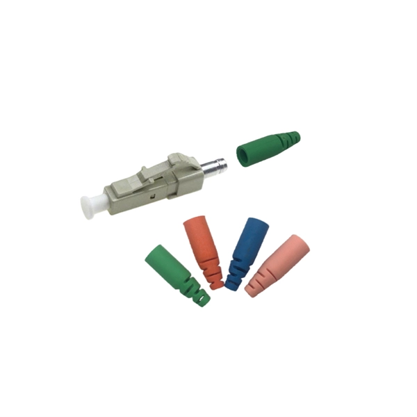
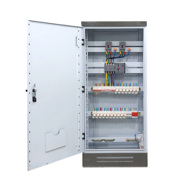
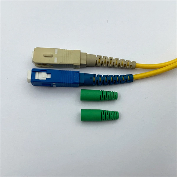
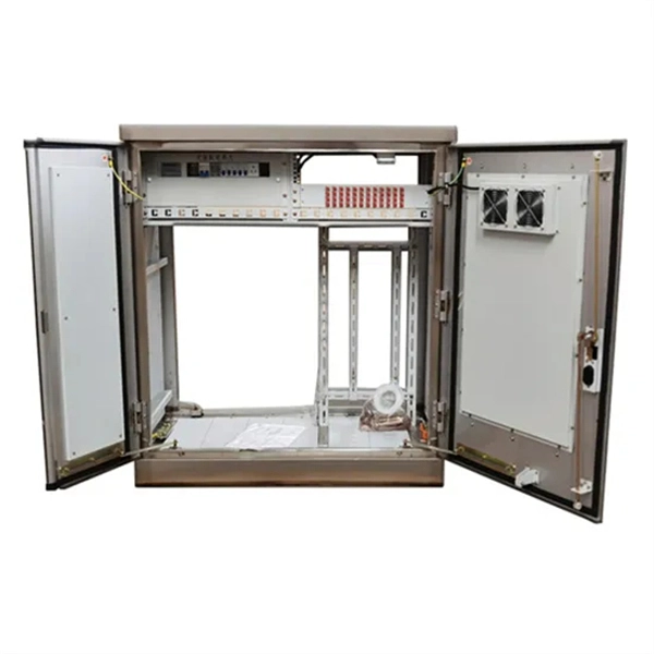
A distribution box, also known as a fiber distribution hub or optical distribution box, is a larger enclosure designed to manage and distribute fiber optic cables to multiple endpoints. It serves as a central point for connecting and organizing numerous fiber optic. Although all three are related to fiber connection and management, their installation locations, functional roles, and positions within the network architecture are fundamentally different. Confusing these devices may lead to non-standard cabling at best, and serious challenges in network. In modern FTTH (Fiber to the Home) and optical communication networks, three types of fiber distribution products are widely used: Splitter Distribution Box, ODF (Optical Distribution Frame), and Fiber Terminal Box. The functions of the four connectors can be. First, let us learn the common point among ODF, fibre optic termination box and fiber optical distribution box, actually, they have similar function, we sort out them as following 4 aspects: 1. fiber termination and optical signal splitting 4. What is the difference between these fiber boxes.
[PDF]
It provides a general plan for spectrum use and the basic structure to ensure efficient use of the spectrum and the prevention of radio frequency interference between services. Learn about the market conditions, opportunities, regulations, and business conditions in tajikistan, prepared by at U. Embassies worldwide by Commerce Department, State Department and other U. agencies' professionals Information and Communication Technologies (ICT) Tajikistan's ICT sector is. Satellite Internet Market Growth The global satellite internet market is experiencing steady growth, driven by increasing demand for reliable connectivity in remote and underserved areas. Through use of the table, manufacturers will have a guide to where in the spectrum to design and build equipment, and. Ministry of communications of Republic of Tajikistan We have an excellent working relationship with the Tajikistan Telecom Wireless Regulatory Authority, officials at Ministry of communications of Republic of Tajikistan. This means that we can ensure all your applications for Wireless Regulatory. On 7 April 2025, in Dushanbe (Tajikistan), Intersputnik, at the invitation of the Communication Service under the Government of the Republic of Tajikistan, attended the International Forum “Digital Transformation: Prospects and Solutions”. Intersputnik Director General Ksenia Drozdova held a.
[PDF]
This section provides a list of the top 10 Optical Attenuator manufacturers, Website links, company profile, locations is provided for each company. Viavi Solutions, Inc. DiCon Fiberoptics, 3. What Is an Optical Attenuator? What Is an Optical Attenuator?. According to our (Global Info Research) latest study, the global Optical Attenuators market size was valued at US$ million in 2024 and is forecast to a readjusted size of USD million by 2031 with a CAGR of %during review period. In this report, we will assess the current U. North American market for Optical Attenuators was valued at $ million in 2024 and will reach $. Optical attenuators are devices designed to reduce the optical power of a light beam or signal by a specific ratio (attenuation factor), typically expressed in decibels (dB). Unlike simple beam blockers or shutters, attenuators are intended to maintain the temporal waveform and usually the mode. The VOA series is a highly compact and cost-effective variable optical attenuator designed for efficiently testing and characterizing optical communication systems and optical components, featuring low insertion loss, fast attenuation speed, and built-in output monitoring.
[PDF]
from outside the US. EMEA Specific: +49 (0) 228 7489 201 HCS and GiHCS are registered tradema time without notice. This document is for informational purposes only and is not intended to modify or supplement any OFS warranties or specifications relating to any of its. from outside the US. STFOC uses our patented cable jacket construction designed to protect the fiber in the harsh subsea environment. Non-KinkTMSTFOC has a patented design to protect. CommScope bundles hybrid cabling to your custom specifications, using our high-performance fiber-optic, unshielded twisted pair and coaxial cables. Devices deployed at the network edge—a 5G radio, a security camera, or an industrial sensor—require high-speed data connectivity and power. It is technically possible to have a separate fiber and electrical cable, but it adds complexity, cost, and maintenance overhead. Optical hybrid cables address. challenge—OCC has what you need. Our team will make sure the configuration is tailored to your needs and will provide a detailed quote. Email us using the Request a Quote below, or give our team a call. Drive, Avon, CT 0600 erat ing Bend Radiu erat ing Bend Radius Cons from outside the US. Teledyne ODI ofers a comprehensive line of fiber optic and electro/optic hybrid wet mate interconnect products. Wet mate connectors are available in ROV Mate, Stab Mate and Manual Mate configurati sm.
[PDF]
1x9 transceivers are the earliest and oldest-style optical modules. Initially created in the 1990s, they aimed at 100M/1G Ethernet, Fibre Channel, ATM, FDDI, SDH/SONET, and video applications. Then, they were gradually replaced by more advanced and intelligent GBICs, SFPs . Next, we will introduce the three main features of the optical module: The package form is the most important feature of the optical module. The earliest package form was 1*9, and then GBIC, SFF, SFP, Xenpak, X2, XFP, etc. came one after another. Due to the limitations of the era, the 10G optical. An optical module is a typically hot-pluggable optical transceiver used in high-bandwidth data communications applications. The unsung heroes behind this "data voyage" are optical modules—the "optical communication translators" that precisely convert electrical and optical signals. From. Before the 1990s, there was no concept of the optical transceiver industry, and equipment manufacturers independently designed and developed optical transceivers with no uniform standards for size and mechanical interfaces, resulting in poor compatibility and connectivity issues for telecom.
[PDF]

1: Use kevlar scissors to cut the cable at the middle. We'll splice the two pieces back together in an exercise and put new connectors on the bare ends in another exercise. Marcel Buijs, EMEA Business Development, Technical Sales, Fiber Optic Center, Inc. with over twenty-five years in the photonics industry, brings the latest information on making the ultimate fiber optic product and improving process yield. Without question, good stripping techniques in your fiber. Use the Wire Stripper/Splitter to strip a variety of fiber optic and coaxial cables up to 14 mm in diameter. This stripping tool provides a comfortable and secure grip to help make the fiber stripping process easy and efficient. In our continuing discussion of installing FO cables, let's use a step-by-step approach in detailing how to strip and clean indoor and. An Optical Fiber Stripper is arguably the most fundamental hand tool for any technician working with fiber optic networks. In an industry where precision is not just a goal but a requirement, the quality of your stripping tool directly impacts signal integrity, network reliability, and overall. Optical fibers are typically protected with fiber coatings made from polymers such as acrylate, silicone or polyimide. For splicing, connectorization or other processing, these coatings must be removed. Fiber strippers are precision tools that reliably and cleanly remove a defined length of coating. Safety Rules - Read before beginning any exercises.
[PDF]
Optical fibers may be connected by connectors typically on a patch panel, or permanently by splicing, that is, joining two fibers together to form a continuous optical waveguide.OverviewAn optical fiber, or optical fibre, is a flexible or plastic that can transmit from one end to the other. Such fibers are widely used in, where they permit transmission over longer distances a. and first demonstrated the guiding of light by refraction, the principle that makes fiber optics possible, in in the early 1840s. included a demonstration of it in his publi. Optical fiber is used as a medium for and because it is flexible and can be bundled as cables. It is especially advantageous for long-distance communications, because propagates.
[PDF]
GPON uses passive optical network (PON) is a access in which a single optical fiber from a central location is shared by multiple end users through one or more in series (cascaded). Unlike traditional fiber connections, PON systems distribute optical signals from an (OLT) to many (ONUs) or (ONTs) without requiring active electronic equipment in the distribution network. The absenc.
[PDF]

Chapter 2, to profile the top manufacturers of Low Friction Butterfly Optical Fibre Cable, with price, sales, revenue and global market share of Low Friction Butterfly Optical Fibre Cable from 2019 to 2024. Explore butterfly fiber optic cables with G657A1 technology, available in single-mode and outdoor options. Order online starting at $0. 04 per unit with a minimum order of 2 pieces. Ideal for wholesalers and distributors seeking high-quality communication cables. The global market for Butterfly Cable was estimated to be worth US$ million in 2023 and is forecast to a readjusted size of US$ million by 2030 with a CAGR of % during the forecast period 2024-2030. The Global Info Research report includes an. Looking for high-quality Optical Fiber Cable Flat Type Butterfly 1 Core G657A LSZH FTTH Drop Cable? Look no further! We are a factory specializing in manufacturing this premium product. We are the real manufacturer with 18. This report provides an in-depth analysis of the market for optical fibers, bundles and cables in Panama. Within it, you will discover the latest data on market trends and opportunities by country, consumption, production and price developments, as well as the global trade (imports and exports). Fiber Core and Cladding: Choose from a variety of core and cladding diameters to optimize performance for your specific.
[PDF]


