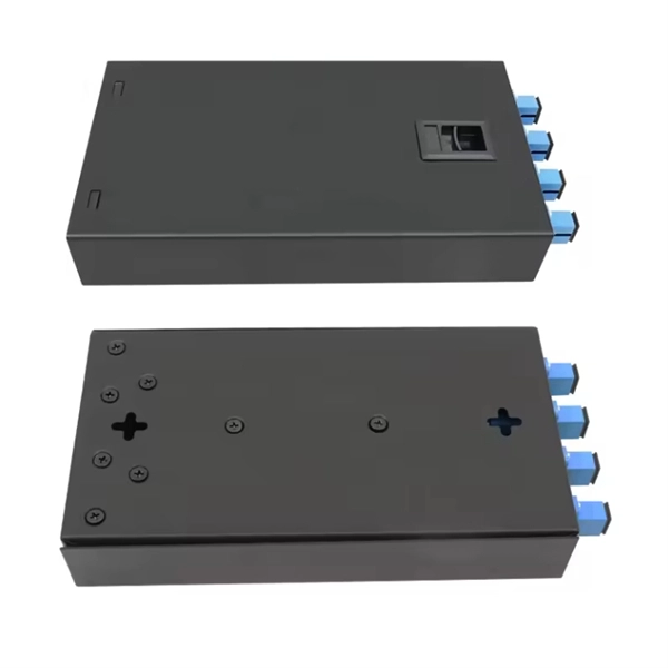
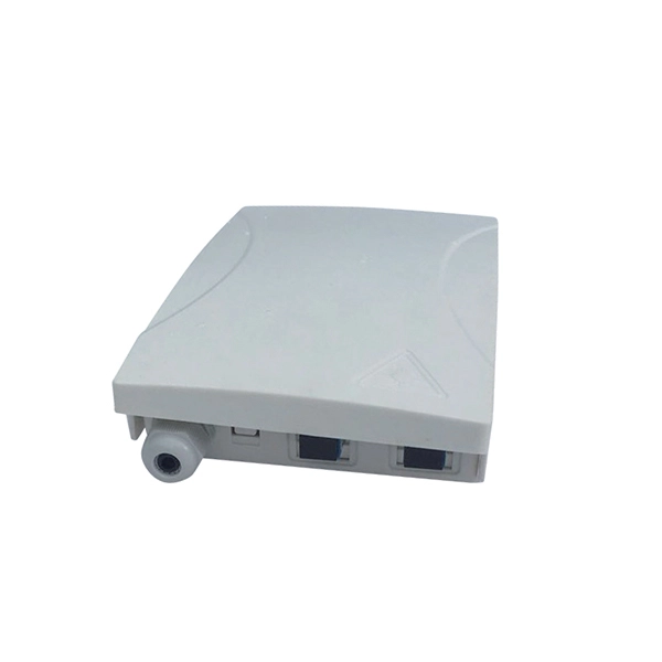
First, connect each pre-terminated fiber optic cable to the adapter panel separately, making sure the ports correspond one-to-one; then fix the fiber optic adapter panel to the front panel of the distribution box with the bend radius control clip. In general, installing the optical fiber distribution box can be divided into three steps: installing the optical fiber distribution box on the rack, introducing the optical cable into the optical fiber distribution box, and planning the optical fiber path in the optical fiber distribution box. The. Bottom installation: Select a proper installation position in the equipment room and drill four holes in the floor according to the dimensions shown in the manual. Fix the rack to the ground with expansion bolts. Top installation: Dimensions of four connection holes on the top according to the. The Optical Distribution Box (ODB) is high-density 2-in-2-out fiber box solution. Designing with a compact size of 340x220x100mm, the cabinet accommodates 1x2,1x4,1x8 and 1x16 etc. The 4 ports are sized for main cable from 9 to 16mm in diameter, along with 16 3mm cables. Accessory Kits:. Install the optical fiber distribution box on the rack. Ensure that the box is installed firmly and horizontally, and the deviation of perpendicularity is not greater than 3mm.
[PDF]
OSFP, or Octal Small Form-factor Pluggable, is a high-speed transceiver form factor designed for next-generation data center networking. Compared with previous generations of optical modules, OSFP is optimized for higher bandwidth, better thermal performance and denser port. Among the various 400G optical transceiver form factors, OSFP stands out as a next-generation form factor specifically designed for high-speed Ethernet, offering clear advantages. This article introduces the fundamental concept and key characteristics of 400G OSFP Ethernet optical transceivers, and. Optech, a Taiwan-based optical transceiver manufacturer, provides professional 400G OSFP and 800G OSFP solutions designed for AI, cloud, high-performance computing, data center and advanced networking applications. Understanding MSA is critical for compatibility validation, cost. As data centers transition from 400G to 800G interconnects, bandwidth demand, power efficiency, and thermal constraints have forced the industry to look beyond traditional form factors. Designed to support 400 Gigabit Ethernet transmission with improved thermal performance and higher power capacity, OSFP modules are widely adopted.
[PDF]
The Malian government has entrusted the extension of the national fibre optic network to China International Telecommunication Construction Corporate. With a total cost of US$117. 3 million, the extension covers Mopti, Koro, Timbuktu, Gao, Ansongo and Labenzaga, and is estimated. The Malian government seeks to strengthen the national telecom infrastructure as part of its digital transformation ambitions. The aim is to gradually include about 65% of the population who still lack access to the internet. According to Agence Ecofin, the work will be carried out as part of a USD117. 3 million USD, the project was approved by the Council of Ministers on Wednesday January 3. As part of the project, Mali will deploy 817km of fibre optic networks, including 420km of Mopti-Gao path, 199km of Mopti- koro-bi path (bordering.
[PDF]

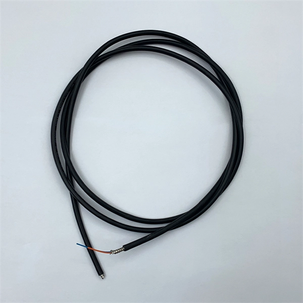
This article outlines five specific steps for repair: 1) Identify the break; 2) Cut out the damaged section; 3) Strip the cable; 4) Trim the fiber ends; 5) Test the repair. DIY fiber optic cable repair kits are increasingly popular for those who prefer home repairs. This guide covers the essential tools and step-by-step procedures for low-loss fiber optic cable repair. Construction Activities: Accidental damage during construction. While a cut or damaged fiber optic cable can temporarily take your network down, it is possible to quickly fix the cable with the right tools. This wikiHow article will teach you how to splice a cut fiber optic cable back together with a fiber optic stripper and cutter and a fiber optic crimper. These cables consist of a core (glass or plastic) that carries light signals, surrounded by cladding to reflect light inward, a buffer for protection, and an outer jacket for durability. The actual steps may vary depending on the cable and/or connectors. Fiber optic cables are typically damaged in one of two ways: A premade fiber optic cable suffers connector damage when too. Don't let cable woes ruin your streaming binge or video conference; instead, explore these six proven ways to troubleshoot and fix your optical cable issues. Before diving into solutions, it's crucial to understand what an optical cable is and how it works. Begin by identifying the damage, which can be done using an Optical Time Domain.
[PDF]
Fiber-Mart offers most affordable high performance MEMS optical switches. The MEMS technology offers extremely low electrical power consumption, high durability (> 1x10^9 cycles), no stiction, and high resistance to shock & vibration. Sercalo's optical MEMS switches are the best choice for optical switches in Network supervision and optical test and measurement because they exhibit solid state reliability, ultra small insertion loss and long-term stability. Since 1999 Sercalo Microtechnology Ltd. supplies optical MEMS solutions. These MEMS single mode switches are designed to be easily integrated into optical systems. The switch is packaged to. MEMS-based switches offer high reliability that passed well over 10⁹ cycles of switching tests. The 1D motion MEMS mirror (in or out of the light path) offers low crosstalk or high on/off ratio, fault-safe latching, free space platform. The 2D. Or specify any custom connector requirement Download the Optosun Optical switch Mems PDF - Opens in new window. Orbray's MEMS (Micro Electro Mechanical System) Optical Switch are designed a small footprint package with providing low insertion loss, flat wavelength dependence loss (WDL), low polarization dependence loss (PDL) and performing less than 1ms/10ms switching speed. Well designed by the professional engineers, MEISU's capacitive MEMS switches are all featured with compact size, high channel count and long life time.
[PDF]

Mechanical Optical Switches: Switching times typically range from 1-10ms, suitable for long-distance transmission scenarios where latency is not critical (such as backbone network protection switching). Solid-State Optical Switches: Based on thermooptic or electrooptic effects, response. We lead the industry in optical switch technology, delivering the lowest insertion loss (0. 2 dB), fastest switching speed (10 ns), broadest wavelength range (300–2400 nm), widest fiber compatibility, highest optical power handling (50 W), and space-qualified reliability. Backed by over 25 years of. Use this optical switches buying guide to compare major types, define selection criteria, and find suppliers: Professional purchasing of high-value photonics products is a substantial responsibility, where a structured decision-making process is essential. RP Photonics offers a lot of help: Get. This document is a troubleshooting and selection guide for common optical switch failures, compiled based on over 500 field cases. These switches are built on proven, reliable optomechanical technology that has seen more than 30 years of successful operation. Each. The POLATIS ® Series 7000 384x384 all-optical circuit switch is designed to meet the most demanding applications with exceptionally low optical loss, compact size, and fast switching speeds. With support for Software-Defined Networks (SDNs) via embedded NETCONF and RESTCONF control interfaces, the.
[PDF]

Key components of a Passive Optical Network include the Optical Line Terminal (OLT), Optical Network Unit (ONU) or Optical Network Terminal (ONT), Optical Distribution Network (ODN), and Optical Splitters. An OLT is a device used to interface between the service provider's central. The designation “passive” separates these components from active devices, such as lasers, amplifiers, or switches, which rely on electrical power to boost, regenerate, or electronically route a signal. Passive components operate solely by exploiting the fundamental physical properties of light. PON primarily utilizes a point-to-multipoint topology and fiber optical splitters to transmit data from a single point of transmission to multiple user endpoints. The key advantages of PON lie in its ability to offer remote, high-bandwidth, and efficient network connections. Key components of a. Some of the most common optical passive components include optical couplers, optical splitters, optical filters, optical connectors, optical attenuators, optical circulators, optical isolators, optical switches, and optical add/drop multiplexers. A. A device in a passive optical network is something that the transceiver transmits information through, like a modem that sends information through fiber-to-the-home. By eliminating powered components between the service.
[PDF]
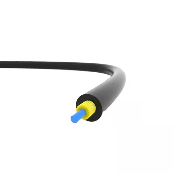
A fiber-optic cable, also known as an optical-fiber cable, is an assembly similar to an but containing one or more that are used to carry light. The optical fiber elements are typically individually coated with plastic layers and contained in a protective tube suitable for the environment where the cable is used. Different types of cable are used for in different applications, for exa.
[PDF]
Cost ranges for a residential fiber optic cable run typically span from $1,000 to $12,000, with most projects landing in the $3,000–$8,000 band. The main drivers are trench depth and length, whether the line is buried or aerial, and the in-home termination requirements. The main cost drivers are materials, installation time, and environmental factors that affect trenching, conduit, and terminations. This article provides cost. Installing an optical fiber network is a significant investment that requires careful financial planning. Whether you're upgrading an existing system or starting from scratch, understanding the costs involved can help you allocate your budget wisely. This guide will walk you through the key factors. How Much Does Fiber Optic Cable Cost per Foot? On average, commercial projects range from $5,000 to $20,000 per mile underground and $40,000 to $60,000 per mile for aerial deployment. Individual business connections often cost between $15,000 and $30,000 for 100–200 network drops. Hiring. Homeowners typically pay a broad range for running fiber optic cable from the street to a residence, with the main cost drivers being trenching or aerial installations, cable material, labor time, and permit requirements. The price also varies by fiber type (GPON vs. The price or cost to install fiber reflects material choices, labor hours, and local regulations, with per-mile and per-ft metrics common in.
[PDF]

When selecting a 48 core fiber optic cable, prioritize single-mode over multimode for long-distance, high-bandwidth applications such as telecom backbones or data center interconnects. Look for cables with loose tube construction, robust armor (if outdoor use), low attenuation (<0. 4 dB/km at 1310. • Fiber optic cables are often custom cut to match required lengths for each cable run, or you can order a reel matching your total length and cut segments yourself. It's advisable to include a safety buffer when ordering, with an additional 10% being common practice, despite careful measurement of. Fast data transmission, thinner, lighter cables and long signal range are just a few of the benefits that make fiber optic cable a solid choice for corporate data networking and telecommunications. Fiber cores are the heart of fiber optic cables, transmitting light signals that carry data. Made from either high-quality. But when it comes to selecting the right fiber optic cable for your environment, there are several key considerations and a variety of attributes to choose from, ranging from type of fiber and strand count to construction and application. Unlike copper wires, which are limited by lower data transmission speeds, shorter transmission distances, and higher susceptibility to electromagnetic interference, fiber optic cables offer unparalleled performance and can.
[PDF]

Managing optical attenuation helps keep your signal safe. Clean your optical connectors so you do not lose. Optical Signal Attenuation is the single greatest factor limiting the distance and performance of your network. Understanding it is crucial for anyone involved in data centers, telecommunications, or enterprise networking. This guide will demystify signal loss, explore its causes, and show you how. In high-speed environments, where the optical link budget is measured in fractions of a decibel, diagnosing and eliminating unexpected loss is the network engineer's most critical task. This field guide provides a systematic, step-by-step approach to troubleshooting and resolving the most common. Signal loss in Fiber Optic networks can make data slow. It can also break your connection. You should fix it fast to get speed and stability back. > You can solve this with simple steps. Signal Degradation (Loss of Light) When the signal quality degrades, it could be a sign of attenuation or excessive loss in the system. The signal might become weaker, resulting in slower speeds or dropped connections. -. Fiber optic networks are celebrated for their speed and reliability, but even the best systems can encounter problems. When issues like signal loss, slow speeds, or intermittent connectivity arise, systematic troubleshooting is key. Things like impurities in the fiber core and reflections at the core-cladding edge cause this drop.
[PDF]

This article will give you an overview of the use cases for fiber-optic networking, some of the terms used in fiber networking, and suggestions for setting up a fiber network. Once you understand the basic concepts, you can check out my Recommended Equipment section toward. Fiber tapping is a network tap method that extracts signal from an optical fiber without breaking the connection. Tapping of optical fiber entails diverting some of the signal being transmitted in the core of the fiber into another fiber or a detector. Fiber to the home (FTTH) systems use beam. Optical fiber is a technology used to transmit data by sending short light pulses along a long fiber, which is typically made of glass or plastic. In optical fiber communication, metal wires are preferred for transmission because the signals travel more safely. Optical fibers are also resistant to. Photo: Light pipe: fiber optics means sending light beams down thin strands of plastic or glass by making them bounce repeatedly off the walls. This is a simulated image. Note that in some countries, including the UK, fiber optics is spelled "fibre optics. " If you're looking for information online. This manual covers everything about fiber optic cables, how they work, where they are used, and what is new in this area of technology. The choice of fiber optic cable depends on the specific needs of the application, as well as the.
[PDF]

The receiver of an optical module has an overload point. Therefore, an optical attenuator is required to reduce the optical power. By introducing a precise and constant amount of optical loss, it ensures that the incoming signal remains within the optimal operating range of the receiver. A. Average optical power refers to the optical power outputted by the optical module's transmitter under normal working conditions, which can be understood as the intensity of light. The transmitted optical power is related to the proportion of "1"s in the transmitted data signal; the more "1"s, the. The receiver of an optical module has an overload point. If the optical power received by the receiver is excessively high, the optical module will be burnt. In addition, during signal transmission in a WDM system, the. 📦 For purchasing, use the RP Photonics Buyer's Guide for optical attenuators. It provides an expert-curated supplier directory, buyer-focused technical background information, and structured selection criteria to support professional procurement decisions. Optical attenuators are devices that. An optical attenuator, or fiber optic attenuator, is a device used to reduce the power level of an optical signal, either in free space or in an optical fiber. Optical internetworks are data networks composed of routers and data.
[PDF]