A distribution box, also known as a fiber distribution hub or optical distribution box, is a larger enclosure designed to manage and distribute fiber optic cables to multiple endpoints. It serves as a central point for connecting and organizing numerous fiber optic. Although all three are related to fiber connection and management, their installation locations, functional roles, and positions within the network architecture are fundamentally different. Confusing these devices may lead to non-standard cabling at best, and serious challenges in network. In modern FTTH (Fiber to the Home) and optical communication networks, three types of fiber distribution products are widely used: Splitter Distribution Box, ODF (Optical Distribution Frame), and Fiber Terminal Box. The functions of the four connectors can be. First, let us learn the common point among ODF, fibre optic termination box and fiber optical distribution box, actually, they have similar function, we sort out them as following 4 aspects: 1. fiber termination and optical signal splitting 4. What is the difference between these fiber boxes.
[PDF]
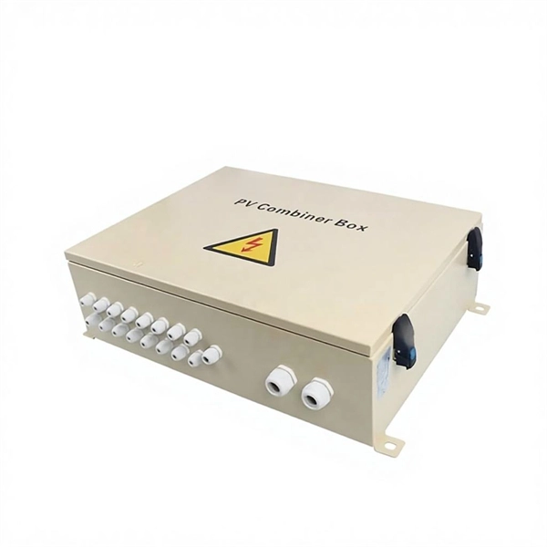
With 2 main cable ports and 12 drop cable ports, it features separate compartments for splicing and patching, allowing easy connection of drop cables without disturbing the spliced fibers. Suitable for wall or pole mount applications. FBR-11608 Fiber-Optic Distribution Box, 12-Core is a high quality product by Bud Industries used for electronic enclosure applications. The 12 Core Fiber Optic Distribution Box is meticulously crafted using high-quality ABS+ material, guaranteeing exceptional protection and achieving an impressive IP 65 protection level. This sturdy. Weidan Electronics fiber access distribution box is able to hold up to 12 subscribers. It is used as a termination point for the feeder cable to connect with drop cable in FTTx network system. It integrates fiber splicing, splitting, distribution, storage and cable connection in one solid. Fiber distribution box is suitable for the wiring connection of optical cable and optical communication equipment, through the adapter in the wiring box, the optical jumper leads the optical signal, and realizes the optical wiring function. Choose MellaxTel for custom Fiber Optic Distribution Boxes – pre-installed or not. The fiber splicing, splitting, distribution can be done in this box, and meanwhile it provides solid.
[PDF]
A Fiber Optic Termination Box is designed to secure and organize fiber optic connections, typically by linking fiber cables to an optical device through a patch cable. It can also function as a fiber optic distribu.
[PDF]

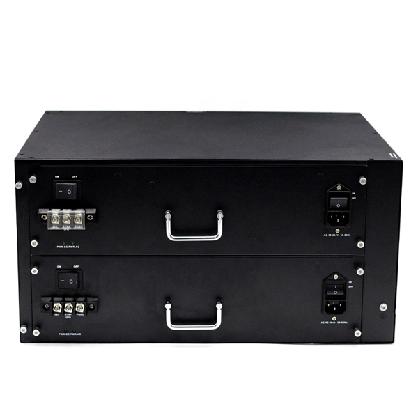
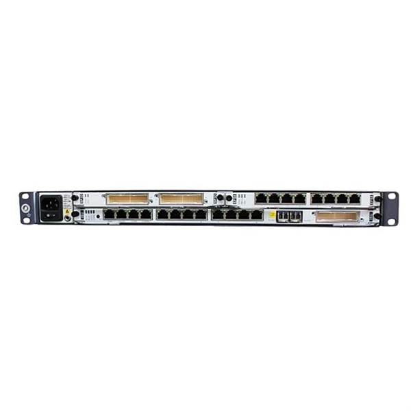
With a modular structure and precise LC/APC interface design, the 144‑core ODF supports efficient network expansion and simplified maintenance, making it ideal for telecom operators and integrators seeking scalable and professional fiber management. The ODF Fiber Optic Distribution Frame LC/APC-144 core is a high‑density optical fiber management solution designed for central offices, data centers, FTTx networks, and system integration projects. Engineered by Fenxi Optoelectronics Technology, this ODF delivers reliable termination, splicing. 144Core modular optical fiber distribution frame is used where termination and connectivity of 144fibers (high density) is required. The frame design is based on a 4U rack unit height. This 144C modular ODF is composed of 12pcs pre-loaded 12C splicing and patching unit that includes FC/SC/ST/duplex. High density 144 cores fiber optic panel integrates optical fiber fusion, disk storage and wiring. Each fusion module can be extracted separately, meeting the requirements of off frame or on frame operation. They allow you to group and terminate fiber at a convenient location.
[PDF]
This guide explains what a fiber optic termination box is, how it works in practice, where it is typically installed, and how to choose the right model for different network environments. What Is a Fiber Optic Termination Box?. A Fiber Termination Box, also known as a Fiber Distribution Box, is a crucial component in fiber optic networks. It serves as a termination point for optical fibers, providing a secure and organized space for connecting and managing fiber optic cables. It functions as a junction between the incoming fiber cable and the outgoing customer-side fiber cable, where one fiber can be spliced, patched. A fiber optic termination box is a core component in modern fiber optic networks, providing a secure and organized point for fiber termination, splicing, and distribution. It is widely deployed in FTTH, FTTB, and other access networks to ensure stable signal transmission from backbone cables to end. Fiber termination box (FTB), also known as optical terminal box (OTB), generally refers to a distribution box specially designed for fiber cable management (fiber patch cables/pigtails) in FTTH applications. To ensure consistent performance and longevity, it is essential to adhere to strict technical specifications.
[PDF]

In this guide, we'll walk you through the entire process of preparing fiber optic cable for splicing and termination to fiber connectors. We'll explore the necessary tools, safety precautions, and step-by-step procedures for cable connectors, mechanical and fusion. At the heart of any robust fiber optic network lies a crucial process: Preparing a fiber cable for termination of a connector or splice. Two types of splices are used in fiber optic cabling one is Mechanical the other is Fusion. Whether you're installing a new network, expanding an existing one, or. Splicing fiber optic cable is an extremely important phase for making dependable, high-speed communication infrastructures. Regardless of the type of fiber network you're deploying, be it for telecom, enterprise data centers, or smart city infrastructure, fusion splicing provides the benefits of. Think of a fiber optic cable splice as the seamless stitching that keeps data flowing through the delicate threads of a network—like a master tailor joining fabric with precision. This article explains when. We terminate fiber optic cable two ways - with connectors that can mate two fibers to create a temporary joint and/or connect the fiber to a piece of network gear or with splices which create a permanent joint between the two fibers. These terminations must be of the right style, installed in a. So in essence, fiber optic splicing is a process used to join two separate fiber optic cables together.
[PDF]
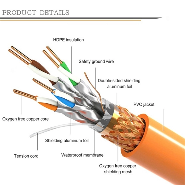
Strip the cable the required length, minimum 0. 5 meter or more, to establish easy and safe installation with enough buffer size. Pass the stripped cable into the upper side of the splice tray. Fix the cable strength member (3) on part (2) and stabilize with cable fixing part. To establish easy and safe installation put the box where it will be installed and measure the required length of the cable. 5 meter or more, to. Lockable Cable inputs: 2x 12mm - 16x Space for 1x16 SC splitter or 1x32 LC splitter 1. Cable fixing Instert the stripped cable through the cable entry port and fasten the FRP element(s) to the block. The outher coating should be fasten useing the steel hops. Do not fasten too. Stripping and preparing fibre optic cables for termination is a critical step in the installation and maintenance of fibre optic networks. Firstly, it is important to consider that when stripping multi-layer cables for connectorization, each layer must usually be stripped individually, as they all usually need to be stripped to different lengths. Cutting and stripping the cable jacket can be done with a special fiber stripper or a properly set wire stripper as long as it does. Whether it is indoor or outdoor fiber-optic (FO) cable, using a step-by-step approach reduces the chance of fiber damage while ensuring the performance of fibers. In our continuing discussion of installing FO cables, let's use a step-by-step approach in detailing how to strip and clean indoor and.
[PDF]

By dividing a single optical signal from a central Optical Line Terminal (OLT) into multiple outputs for Optical Network Terminals (ONTs) at users' homes, splitters eliminate the need for dedicated fibers to each residence—slashing infrastructure costs while scaling network reach. This guide. Due to the wide range of deployment configurations, this document will provide qualitative differences, but no specific quantitative comparisons. The centralized home run configuration involves running individual fibers from the central office to each customer (see Figure 1). This architecture is. The Fiber Broadband Association has released a guide called “Introduction to Passive Optical Network Splitter Architectures. ” The goal of the guide, which is the latest release in the organization's Fiber 101 series, is to demystify the terminology, configurations, and best practices associated. Passive Optical Networks (PON) have become the backbone of high-speed fiber-to-the-home (FTTH) solutions. Network designers and ISPs aiming for efficiency must focus on effective passive optical network design, with careful consideration of PON architecture planning and splitter placement. This. What is an Optical Splitter? An optical splitter is a crucial passive fiber optic device that splits and combines optical signals. Conversely, it can also combine multiple signals into one. Its primary role is in Passive Optical Networks (PON), which are the foundation of.
[PDF]
Scattering accounts for the greatest amount of attenuation in a fiber cable, between 95 and 97 percent. Light traveling through the fiber interacts with the densities as shown in the light and is then partially scattered in all directions. Fiber optic cables have many advantages, but one of the downsides just like with copper cable, is that it can experience what is called attenuation. Attenuation refers to the loss of light as it travels down the fiber. This can be due to a variety of factors: scattering and absorption, intrinsic. This attenuation is inevitable, so the smaller the attenuation value, the longer the transmission distance of the same optical power. The better the quality of this fiber patch cable. It indicates the amount of signal reflected back. At TREND Networks, we are frequently asked how much loss is allowed when conducting testing on fiber optic cabling. Unfortunately, it is not a simple answer and depends on several factors. So how do you determine acceptable loss? When testing fiber optic cabling, determining acceptable loss is. Understanding fiber loss is vital in maintaining a reliable, efficient network. Understanding it is crucial for anyone involved in data centers, telecommunications, or enterprise networking. Here are the details and instructions about each field and how they contribute to the calculation: 1. Attenuation Coefficient (dB/km): This value represents the inherent signal loss per kilometer of.
[PDF]
For example, in a FTTH network, a single fiber from the telecom provider can serve 32 homes using a 1:32 splitter, eliminating the need for separate fibers to each residence. These unassuming devices enable a single optical signal to be divided into multiple paths, making them indispensable for sharing network resources efficiently—from residential FTTH (Fiber-to-the-Home) connections to large-scale telecom backbones. This guide demystifies fiber optic splitters. You use optical couplers and splitters to split or join signals in fiber networks. These devices help you control light signals well. For example, optical splitters send light to many output ports. It can divide the input optical signal into multiple output optical signals to meet the fiber optic access needs of multiple terminal devices. This type of device plays an important role in passive. A fiber-optic splitter, also known as a beam splitter, is based on a quartz substrate of an integrated waveguide optical power distribution device, similar to a coaxial cable transmission system. The optical network system uses an optical signal coupled to the branch distribution. The fiber optic. If you've ever wondered how a single fiber from your internet service provider can deliver service to an entire neighborhood or apartment building, you've wondered about the magic of optical splitters. The process of light beam splitting involves.
[PDF]
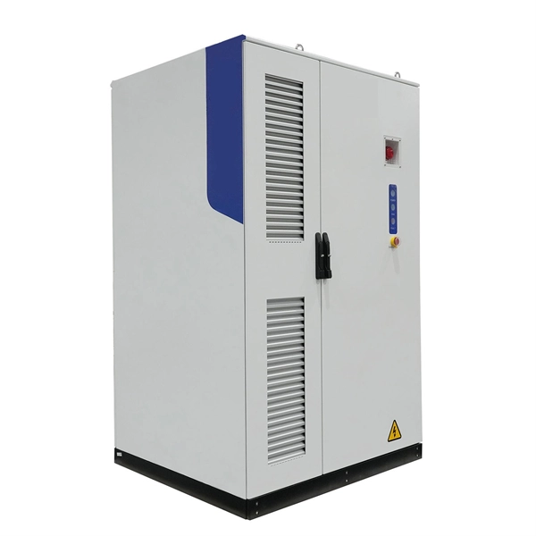
An optical module sends data as light through fiber cables. Light is faster than electricity, making it great for quick communication. The optical module serves as a crucial component in optical fiber communication systems, operating at the physical layer, which is the lowest layer in the OSI model. Its primary function is to achieve optoelectronic conversion by converting electrical signals into optical signals and vice versa. This technology is crucial for fast and reliable data transfer in networks. Optical modules typically have an electrical interface on the side that connects to the inside of the system and an optical interface on the side that connects to the outside. Optical fiber transmission forms the backbone of modern high-speed communication networks, enabling the efficient transfer of massive datasets across vast distances. These modules typically consist of a transmitter, which converts electrical signals into a light signal, and a receiver, which converts the received signal back. In high-speed data networks, the seamless integration of fiber optic cables with SFP (Small Form-Factor Pluggable) modules is critical for reliable signal transmission. SFP transceivers bridge electrical and optical signals, making them indispensable in data centers, telecom networks, and.
[PDF]
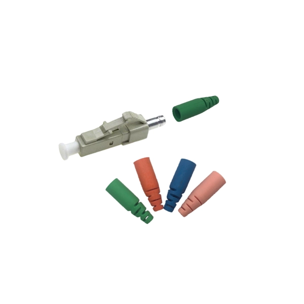
IEC fiber connector standards establish the global specifications for connector geometry, mating interfaces, optical performance classes, and mechanical testing across all fiber network environments. Optical connectors are used to connect optical devices to other optical devices or systems. However, each connection introduces a certain amount of insertion and return loss that. Connectors play an important role in Enterprise network architecture. They give you the power to add, drop, move, and change the network. is a small cylinder used to mount. The Fischer FiberOptic Series offers robust and faultless optical performances in any conditions. Combined with easy use, cleaning and maintenance. Tested for harsh and extreme environments (Norm IEC 61753-1 Cat. These standards ensure that passive fiber-optic components remain interoperable, stable, and. designed for diverse fiber optic applications. But what exactly sets a fibe optic connector apart in terms of its merits? The primary purpose of a fiber optic connector is to terminate the ends of fiber optic cables, ensuring they can be int rconnected reliably with minimal optical loss. After. Fiber optic technology is used in ever-increasing applications due to its inherent advantages (lower weight, EMI/RFI immunity, higher bandwidths and distances) over copper. There are many.
[PDF]

Huawei's fiber to the room (FTTR) solution extends fibers to rooms and provides various gigabit Wi-Fi 6 master/slave FTTR units, all-optical components, and optical cable routing tools. This enables home users to enjoy stable gigabit Wi-Fi experience from anywhere in the home. FTTR is generally an extended FTTH (Fiber To The Home) solution. Drop optical cable terminates at ATB (Access Terminal Box). A patch cord of 1 or 2 m. Huawei will soon be selling its "FTTR" system for do-it-yourself fiber optic home cabling in Germany. Huawei FTTR: Bonding tool for fiber optic installation. A special glue. Fibeye provides FTTR(Fiber to the room) solutions, We specialize in Huawei-adapted FTTR solutions that can help you tap into new markets and grow your business. What is FTTR FTTR(Fiber-to-the-room), is an innovative solution that allows telecom operators to bring optical fibers directly into. Guess what, I spotted Huawei's transparent fibre optic offering! The best Wi-Fi is wired Last year, I wrote about Singtel's FibreEverywhere offering, which allows homeowners to install high-speed wired cabling in every room - without any drilling or trunking. Poor Wi-Fi coverage at home is a common. Watch the video to discover how to use the Huawei FTTR fiber installation kit to route transparent optical cables.
[PDF]
