
This guide is intended to present the fundamentals of power system design for commercial and industrial power systems. A distribution board, also known as a panel board or breaker panel, is an enclosure that houses electrical components such as circuit breakers, fuses, and busbars. Its primary function is to distribute electrical power from a main supply to various circuits while providing protection against. These Distribution Boxes enable decentralized installation of the electronics close to the load. The range of applications extends from pure energy distribution in buildings to building automation and through to industrial plants. SMART DISTRIBUTION BOXES FOR FLEXIBLE BUILDINGS. It is a vital part and central hub of any electrical system. Whether it's a home, office, or factory. Electrical distribution system design is a critical aspect of industrial facility engineering that determines how electrical power is delivered from the utility service to end-use equipment. A well-designed distribution system provides reliable power, adequate capacity, proper protection, and. In industrial power distribution systems, cable distribution boxes (also known as power distributor boxes, distribution electrical boxes, or electrical power distribution boxes) are the core hub of power transmission, branching, and protection. Its layout directly affects the efficiency of the.
[PDF]

In this paper, various operational factors affecting 100G transmission over G. D fiber-cables are discussed to make the right fiber selection for the long-haul network. Selecting appropriate G. 652 fibre was originally optimized for use in the 1310 nm wavelength region but can also be used in the 1550 nm region. This is the latest revision of a Recommendation that was first created in 1984 and deals with some relatively minor modifications. a number of concatenated cable. G. 92% of. Fiber optic cables are the ultimate technology used in data transfer using light waves. They are classified based on wavelength band, core/cladding size, application, and compliance with international standards such as IEC, ITU-T, and TIE/EIA. In the next sections, the real artwork is putting on. This guide explains the most important ITU-T G. 655—to help you make an informed decision for your project, whether it's a long-haul backbone or a final FTTH drop. In the world of fiber optics, not all glass is created equal. The core of every cable—the optical. Because GPON and XGS-PON are deployed in diverse environments, fiber-containing components such as PLC splitters must be evaluated not only by their standard parameters but also by their sensitivity to bending loss, which is critical for maintaining stable optical transmission. The ITU-T defines.
[PDF]

This document discusses the implementation for Cisco Software-Defined Access (SD-Access) deployments for Airports. For the associated deployment guides, design guides, and white papers, refer to the following documents:. The low noise Silent Switcher architecture simplifies design and PCB layout to help streamline development and reduce the chance of a redesign. The compact Silent Switcher solution size supports a range of applications, including industrial, instrumentation and measurement, healthcare, aerospace. AIRPORT ELECTRICAL DESIGN STANDARDS Los Angeles World Airports 1. 1 GOALS The goal of this section is to provide guidance for all electrical work at LAWA. Additional discipline specific guidance related to electrical work can be found throughout the Design & Construction Handbook (DCH). This page provides a quick reference to engineering, design, and construction standards for various airport-related equipment, facilities, and structures. Visit our Series 150 Advisory Circular Library for a complete listing of current advisory circulars. Simpleway's battle-tested hardware ecosystem combines nnounce audio devices with digital signage controllers, creating a unified communication infrastructure built from real airport experience - from routine gate operations to full-terminal evacuations. Discover how nnounce devices create a.
[PDF]

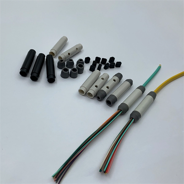
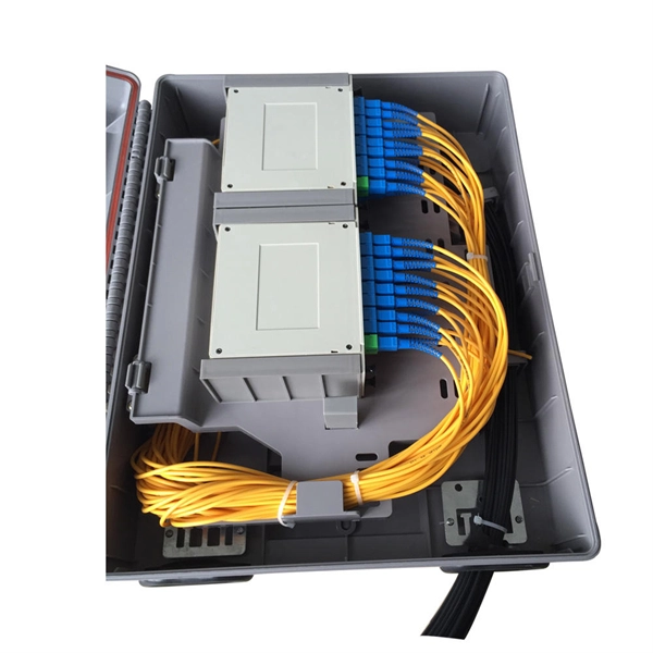
This guide covers everything: what fiber optic pigtails are, how they differ from patch cords, which connector and polish type to specify, how to choose between mechanical and fusion splicing, and the real-world applications where pigtails are the right call. In this guide, we cover the basics of fiber optic splicing, how to perform splicing using two different methods, and finally some best practices to perform good fiber splicing. What is Fiber Optic Splicing and Why is it Needed? – #1. Whether you're building out an ODF. Think of a fiber optic cable splice as the seamless stitching that keeps data flowing through the delicate threads of a network—like a master tailor joining fabric with precision. Whether repairing a broken cable or extending a fiber run, fiber optic splicing ensures light signals travel. Fibre optic splicing is an essential skill in the world of modern telecommunications, offering a reliable method to connect optical fibres for seamless data transmission. As the demand for high-speed internet and robust communication networks continues to grow, learning to splice fibre optics is. In this guide, you will find a chronological description of the fusion splicing process, the principal technical standards, and answers to the real-life questions network engineers and procurement teams may have. Therefore, we will also touch on cost factors, risk management, and best practices in.
[PDF]
Choose the right box based on environment (indoor/outdoor), load capacity, and durability. Check for proper IP/NEMA ratings and material quality. Ensure safe placement: install in dry, accessible areas with good ventilation and at appropriate height (typically ~1. Practice good wiring: secure. An electrical distribution box, also known as a power distribution box, panelboard, or consumer unit, is the core of an electrical system. It has three categories: residential, commercial and industrial electrical distribution boxes, all of which play important roles in their respective electrical. When you install a distribution box, you need a variety of tools to get the job done safely and efficiently. To install distribution box systems, you'll use hand tools such as screwdrivers and pliers. Wire strippers are essential when you install distribution box wiring. A measuring tape and. This guide offers an in-depth exploration of installing electrical distribution boards, highlighting essential steps, safety measures, and the integration of business intelligence tools to optimize your work. Just like travelers need clear pathways and safety protocols, your electrical circuits need proper management to prevent chaos. The National Electrical Code (NEC) requirements might seem like bureaucratic.
[PDF]

In part one of GIGABYTE Technology's latest Tech Guide, we explore the industry's most advanced cooling solutions so you can evaluate whether your data center can leverage them to get ready for the era of AI. 9 thermal guidelines applied to AI data center cooling — H1 high-density class, B200/GB200 implications, and what's coming in the next revision. Liquid. As Artificial Intelligence (AI) and High-Performance Computing (HPC) workloads drive rack densities beyond 50kW, traditional air cooling is reaching its physical and economic limits. Liquid cooling—specifically Direct-to-Chip (D2C) or Cold Plate technology—has emerged as the standard solution for. Modern AI accelerators have dramatically increasing power requirements, with TDPs rising from 300W (V100) to over 1,400W (MI355X) Heat Output = 700W × 0. 5W thermal BTU/hr = 696. Traditional air-cooling methods are struggling to keep pace with cooling the data center. Compute infrastructures for training large AI models are similar to high-performance computing (HPC) systems, which have long been used for demanding tasks in fields such as engineering, scientific research and finance. Industry insiders familiar with the natural progression of the modern data center will.
[PDF]

Based on the need for real-time sag monitoring of Overhead Power Lines (OPL) for electricity transmission, this article presents the implementation of a hardware and software system for online monitoring of OPL cables. OptiSystem is an optical communication system simulation package for designing, testing, and optimizing virtually any type of optical link in the physical layer of a broad spectrum of optical networks, from analog video broadcasting systems to intercontinental backbones. A system-level simulator. Enhance your OTDR training and demonstrations with the portable Fiber Lab MSP. This all-in-one solution simulates P2P, FTTx, and Cell Tower fiber spans in a single unit, while including over 20km of fiber, good/bad splices, 1xN splitter, and reflective connectors. WHY CHOOSE THE FIBER LAB MSP? When. OCSim modules have been proven to provide accurate simulations. The modules which are continuously upgraded are and laboratory simulation experiments. The mathematical model based on differential equations and the methods of. This repository is a Python-based framework to simulate systems, subsystems, and components of fiber optic communication systems, for educational and research purposes. Several digital modulations available (M-PAM, square M-QAM, M-PSK, OOK) to simulate IM-DD and coherent optical systems.
[PDF]

Explore a comprehensive guide to residential electric meter box wiring diagrams, offering clear instructions for safe and efficient installation. A distribution box is the heart of any electrical system. It takes the incoming power and safely distributes it to different circuits throughout your building. However, the key to. Learn how to wire a distribution box step by step! This video shows real on-site footage of electrical installation, demonstrating safe and standardized wiring methods used by professionals. It has three categories: residential, commercial and industrial electrical distribution boxes, all of which play important roles in their respective electrical. Cleaning of the various PXBCM device housings should only be done with power and mains disconnected. A clean dry rag can be used to remove dust. No liquids should be used. Catalog Numbers Catalog Number DescriptionSuffix De- scription Notes PXBCM-MB Meter Base PXBCM-MMS-L09-A Meter Module Strip. full turn-key system solution backed with industry leading reliability and performance. Applications - The minimally invasive retrofit kit enables the opportunity existing remote power infrastructure cross arm, & wiring) providing the total cost of ownership. Failure to strictly adhere to the.
[PDF]

The PL-1000D simultaneously monitors up to 16 fiber strands, eight on the OTDR and eight on the OSA, and operates standalone over dark fiber, lighted fiber, or a third party network without impacting network traffic. The device monitors the entire D. The PL-1000D simultaneously monitors up to 16 fiber strands, eight on the OTDR and eight on the OSA, and operates standalone over dark fiber, lighted fiber, or a third party network without impacting network traffic. The device monitors the entire DWDM C-band spectrum and provides the optical spectrum, OSNR, and OTDR measurements of the fiber. The OTDR locates fiber cut by sending high powered optical pulses into the fiber and creating Rayleigh back-reflections. The returning signals are measured and calculated, indicating the accurate location and intensity of the fault. The OTDR supports GIS (Geographic Information System) using Rest API, enabling precise geographic location of disrupt. The OSA enables the user to monitor the OSNR and optical spectrum of each fiber and shows a full, accurate and detailed picture of the wavelengths used in the fiber. OSADiagram Graphical Display of the OSA, from PacketLight's LightWatch NMS Please contact usfor a quote or further assistance.
[PDF]
Based on analysis on the dispersion of the optical system of a MEMS-based VOA, we provide a method to reduce the WDL significantly with minor revision on the end-face angle of the collimating lens. 📦 For purchasing, use the RP Photonics Buyer's Guide for variable optical attenuators. It provides an expert-curated supplier directory, buyer-focused technical background information, and structured selection criteria to support professional procurement decisions. Variable optical attenuators are. An optical attenuator, or fiber optic attenuator, is a device used to reduce the power level of an optical signal, either in free space or in an optical fiber. The basic types of optical attenuators are fixed, step-wise variable, and continuously variable. Optical attenuators are commonly used in. Applications in broadband optical fiber communication system need variable optical attenuators (VOAs) with low wavelength-dependent loss (WDL). What Are Fiber Optic Attenuators? Fiber optic attenuators, also called optical attenuators, are passive. Optical attenuators are categorized based on their attenuation mechanism and adjustability: Fixed Optical Attenuators: These attenuators reduce the signal power by a predetermined value and are used in applications where a constant level of attenuation is required. It works by dissipating a portion of the optical power passing through it, thereby lowering the overall power level. Fiber optic attenuators.
[PDF]