Main cost drivers include on-site labor, specialized fusion splicing, testing, and any necessary restoration of network performance. This guide provides practical cost ranges in USD with clear low–average–high estimates to help budgeting and planning. Fiber optic splicing costs vary widely depending on project size, location, fiber type, and site conditions. For most commercial projects, expect to pay $50–$150 per fusion splice point — but that number can swing in either direction based on the factors below. The "per splice" rate is the most. There are two primary methods of splicing fiber optic cables: fusion splicing and mechanical splicing. Each method has distinct characteristics and costs associated with it. Fusion Splicing: This method involves aligning two fiber ends and using an electric arc to melt them together, creating a. Adtell Integration is capable of supporting your fusion splicing requirements whether they require Singlemode, Multimode, or Ribbon Splicing. Fusion Splicing Services: Contractor/Customer Fusion Splicing & Installation Services: Adtell integration offers nationwide fusion splicing services. Specifically fiber used for internet. -W2 employee for a decent size telecommunication contractor, all.
[PDF]
With 2 main cable ports and 12 drop cable ports, it features separate compartments for splicing and patching, allowing easy connection of drop cables without disturbing the spliced fibers. Suitable for wall or pole mount applications. FBR-11608 Fiber-Optic Distribution Box, 12-Core is a high quality product by Bud Industries used for electronic enclosure applications. The 12 Core Fiber Optic Distribution Box is meticulously crafted using high-quality ABS+ material, guaranteeing exceptional protection and achieving an impressive IP 65 protection level. This sturdy. Weidan Electronics fiber access distribution box is able to hold up to 12 subscribers. It is used as a termination point for the feeder cable to connect with drop cable in FTTx network system. It integrates fiber splicing, splitting, distribution, storage and cable connection in one solid. Fiber distribution box is suitable for the wiring connection of optical cable and optical communication equipment, through the adapter in the wiring box, the optical jumper leads the optical signal, and realizes the optical wiring function. Choose MellaxTel for custom Fiber Optic Distribution Boxes – pre-installed or not. The fiber splicing, splitting, distribution can be done in this box, and meanwhile it provides solid.
[PDF]

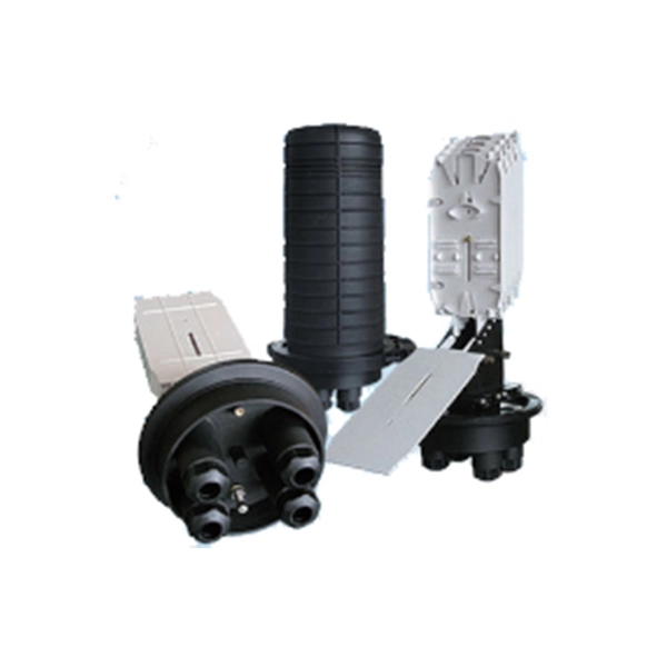
Learn how to install fiber splice trays inside an enclosure step by step. Quick, easy, and essential for fiber pigtail management! https://bit. Unlike fiber connectors, which can be plugged and unplugged, splicing creates a fixed connection that is typically more stable and has lower insertion. This document describes the installation of optical fiber with both single fiber and/or ribbon fiber splices into Optical Splice Enclosure (OSE) metal splice trays (Figure 1). Make sure you read and understand this instruction as well as instructions provided with related assemblies before. By following these detailed steps, the installation of your Fiber Splice Closure will be secure, organized, and maintained, ensuring high performance and longevity of your fiber optic network. Installing a fiber optic splice closure efficiently and effectively requires attention to detail and. How to install the splitter distribution box is the important information we need to know. This article includes the following: 1. Install the fixture 2. Box installation and fixed splitter distribution box 4. Install. Page 5 B (# 7 & 8) enter splice tray # 2. Route the fibers entering the splice tray up to splice point as shown. NOTE : Protection tube from side A enters splice tray from the far end as shown After splicing, close the splice tray and lock the front cover properly with the main and side lock.
[PDF]

Because fiber optic cables don't come in one continuous length, sections must be joined together through splicing. This process fuses two glass strands so light signals can travel through them without interruption. Below is a detailed look at each step of fiber optic network construction, including key terms and methods used across the industry. Engineers and. We are experts in the installation and use of fiber optic cable to residences, apartment buildings, businesses and cell sites. We complete complex construction projects consisting of aerial and underground deployments in varied, often difficult, working environments. Our services include everything. The Fiber Optic Association, Inc. (FOA) was founded in 1995 to help develop the workforce to build the fiber optic networks to support a rapid expansion in communications and the Internet. Delivers state-of-the-art fiber optics solutions by developing high-tech equipment and subcontractor expertise. Utilizes state-of-the-art technologies to splice a wide variety of different. This recommended practices document is a comprehensive manual for optical fiber construction and testing. Sections are included for project management; cable handling, testing and equipment; overhead cable placement; underground cable placement; underground enclosures; bonding and grounding; cable. 4. FO-VC2 JOINT USE - VERICAL MIDSPAN CLEARANCES 48. FO-GB GROUNDING AND BONDING 49.
[PDF]

The document discusses optical detectors used in fiber optic communications systems. It describes the functioning of PIN photodetectors and avalanche photodetectors (APDs). Their performance. An optital detector is a device that converts light signals into electrical signals, which can then be amplified and processed. Such detectors are one of the most important components of an optical fiber communcation system and dictate the performance of a fiber optic communication link. PIN Photodiode A PIN photodiode is a widely. Detectors perform the opposite function of light emitters. The most common detector is the semiconductor photodiode, which produces current in response to. It explains how these devices use optical fibers to measure quantities like temperature, mechanical strain, pressure, and vibrations by detecting changes in light propagating through the fiber. A central focus is on sensors based on fiber Bragg gratings, where the Bragg wavelength is sensitive to. Optical Power Meters: These devices measure the power of optical signals in fiber optic cables. This information helps in maintaining signal integrity and quality across the.
[PDF]

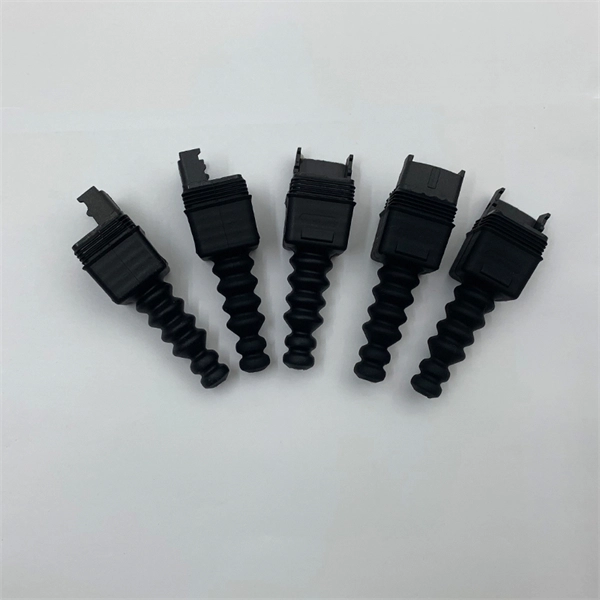
This guide covers everything: what fiber optic pigtails are, how they differ from patch cords, which connector and polish type to specify, how to choose between mechanical and fusion splicing, and the real-world applications where pigtails are the right call. In this guide, we cover the basics of fiber optic splicing, how to perform splicing using two different methods, and finally some best practices to perform good fiber splicing. What is Fiber Optic Splicing and Why is it Needed? – #1. Whether you're building out an ODF. Think of a fiber optic cable splice as the seamless stitching that keeps data flowing through the delicate threads of a network—like a master tailor joining fabric with precision. Whether repairing a broken cable or extending a fiber run, fiber optic splicing ensures light signals travel. Fibre optic splicing is an essential skill in the world of modern telecommunications, offering a reliable method to connect optical fibres for seamless data transmission. As the demand for high-speed internet and robust communication networks continues to grow, learning to splice fibre optics is. In this guide, you will find a chronological description of the fusion splicing process, the principal technical standards, and answers to the real-life questions network engineers and procurement teams may have. Therefore, we will also touch on cost factors, risk management, and best practices in.
[PDF]

Calculate end-to-end loss from cable length, connector and splice counts, and known component losses; verify with a light source + power meter (OLTS). If installed loss exceeds design, reduce connection points, rework poor splices, or use optics with better. This document presents a troubleshooting guide for fiber optic cables once deployed and in regular use. It also includes a list of common fault location items. How to troubleshoot: measure. Fiber optic networks are celebrated for their speed and reliability, but even the best systems can encounter problems. When issues like signal loss, slow speeds, or intermittent connectivity arise, systematic troubleshooting is key. These high-speed, high-capacity communication networks are increasingly replacing copper cables, offering superior performance and. Fiber optic troubleshooting is the systematic process of identifying, diagnosing, and resolving problems within fiber optic communication networks. These networks are the backbone of modern data transmission, offering incredible speeds and bandwidth. However, even the most robust systems can. Fiber optic cables are the backbone of today's high-speed communication networks, powering everything from FTTH broadband to data centers. However, like any technology, fiber optic systems can encounter issues that affect performance. Understanding the common causes and solutions helps maintain.
[PDF]

A fiber is used to support G. 691 with a maximum rate of STM-16 or 10Gbit/s and a maximum transmission distance of 40 km (Ethernet) and STM-256 for G. This document outlines the specifications for a single-mode optical fiber and cable designed for use around the 1310 nm zero-dispersion wavelength, suitable for both the 1310 nm and 1550 nm regions, and compatible with analogue and digital transmission. It details the fiber's geometrical, optical. G. 652 is an international standard that describes the geometrical, mechanical, and transmission attributes of a single-mode optical fibre and cable, developed by the Standardization Sector of the International Telecommunication Union (ITU-T) that specifies the most popular type of single-mode. G. 652 optical fiber is a kind of optical fiber that is widely used in the network. 652 is mainly based on the requirements of PMD and the attenuation requirements at 1383nm. 652D is the type of optical fiber in the optical cable, which represents non-dispersion-shifted single-mode fiber, and is currently the most widely used single-mode fiber in China. This article will provide a detailed introduction to the structure, characteristics, and applications of standard single-mode fiber. G652 is a specification for optical fiber cables. It is part of the International Telecommunication Union (ITU-T) G.
[PDF]
Compared to conventional metallic cables, optical fiber provides an advantage of low loss (~ 0. 2dB/km) and wide bandwidth (several hundred MHz to THz) to enable long-distance, high-capacity communication. Fiber-optic communication is a form of optical communication for transmitting information from one place to another by sending pulses of infrared or visible light through an optical fiber. The light is a form of carrier wave that is modulated to carry information. Fiber is preferred. It was almost a century later before optical-based communication was put to practical use, thanks in large part to the invention of optical fiber and lasers. A laser's stable, highly directional beam of light (emitted from tiny semiconductor windows that measure just a few hundred thousandths of a. In 2020, we celebrated the 50th anniversary of the invention of low-loss optical fiber — an innovation that has transformed the way we connect and that lies at the cornerstone of our communications revolution. In a Corning lab on a Friday afternoon five decades ago, a single strand of glass and a. Fibre optics and optical communications is the use of thin strands of glass for sending information encoded into light over long distances. Total internal reflection prevents light inserted into one end of the fibre from escaping through the sides. Transferring information optically in this way.
[PDF]
Fiber core manufacturing involves preform creation using chemical vapor deposition, followed by precision drawing at 2000°C temperatures with real-time diameter control and protective coating application. Getting into fiber core manufacturing 1 feels overwhelming at first. Single-mode fiber represents the pinnacle of long-distance optical transmission technology. With its precisely engineered small core diameter, SMF enables crystal-clear data transmission across vast distances. The technology is. The ultra-fast internet you rely on every day is made possible through fiber optic cables which are thin strands of glass or plastic. However, you know they go through an extremely complex manufacturing process involving advanced technology, extreme temperatures, and thorough testing. Let's take. Fiber optic cables are a crucial component of modern telecommunications and data transmission systems. Fiber optic technology has revolutionized the way information is transmitted, offering numerous advantages over traditional copper wiring. What makes fiber optic cables special is their ability to. The fiber optic cable core is the fundamental material at the heart of fiber optic cables, enabling the transmission of light signals for high-speed data communication in fiber optic technology. As the primary component that carries light within a fiber optic cable, the fiber optic cable core is a.
[PDF]
Picking up the best router for fiber internet isn't just about going to the market and choosing one of the best wireless routers. Instead, you need to carefully look at its specs, performance, and the type of securit.
[PDF]

President Ibrahim Mohamed Solih highlighted on Friday the importance of connecting the country to the international fibre cable system, stating that it is a crucial step in establishing the Maldives as a hub for technology and innovation. The President's remarks at the inauguration of the Ocean. Today, we're announcing Dhivaru, a new Trans-Indian Ocean subsea cable system that will connect the Maldives, Christmas Island and Oman. This investment will build on the Australia Connect initiative, furthering the reach, reliability, and resilience of digital connectivity across the Indian Ocean. A new domestic Maldivan subsea cable from Dhiraagu and Ooredoo has landed on the island of Hulhumalé in the North Malé Atoll. Dubbed the Domestic Submarine Cable of Maldives (DSCoM), the telecommunications cable has five segments and will connect eight islands in the Maldives including Hulhumale'. Huawei Marine today announced that it has partnered with Ooredoo Maldives to deploy a Nation-wide Fiber Optic Submarine Cable, which will support the country's broadband policy and give the Maldives the most advanced ICT infrastructure in the SAARC region. The nationwide submarine cable utilizes.
[PDF]
Choosing the right fiber optic cable factory is vital to ensuring the performance, longevity, and reliability of your network. This article provides a guide from various dimensions on how to choose the right suppliers and manufacturers, along with a detailed. Selecting the right fiber optic cable manufacturer directly impacts your network's reliability, performance, and total cost of ownership. With the global fiber optic cable market valued at $13. 92 billion and growing at 10. The industry landscape features both global. This article highlights leading fiber optic cable manufacturers in the United States, renowned for their high-quality products and innovative solutions. For procurement managers and network engineers, the challenge is balancing performance, budget, and lead times. But if you want to find the best one, it's a bit difficult. Don't worry, Gcabling will help you. Gcabling, as a leading optical cable manufacturer that can. Based on 2025 rankings from industry sources like Owire and TSCables, the top manufacturers are evaluated on market share, innovation, and global reach. This list incorporates leading players, including Dekam-Fiber, Corning, Prysmian, and CommMesh, which stand out for their contributions to.
[PDF]
