A fiber optic switch allows optical signals to be selectively switched from one fiber to another, while a fiber optic splitter divides an optical signal into multiple signals, allowing it to be transmitted to multiple devices. It is essentially a switch that operates at the optical layer of a network, rather than at the electrical layer. Conversely, it can also combine multiple signals into one. Its primary role is in Passive Optical Networks (PON), which are the foundation of. A fiber optic splitter is a passive optical component that divides a single incoming optical signal into two or more outgoing signals, or combines multiple incoming signals into one. The optical network system uses an optical signal coupled to the branch distribution. The fiber optic. While the splitter doesn't manage or direct traffic like a switch, it does allow multiple devices to access the same network connection. The devices connected to the splitter typically need to be configured to work with the shared connection, and bandwidth may be divided among the devices based on. A passive device used to split or combine signals on fiber optics may be called a splitter, combiner or coupler, but splitter is the most common term. They have been used since the 1980s to create networks and provide the technology for today's passive optical networks used in fiber to the home.
[PDF]

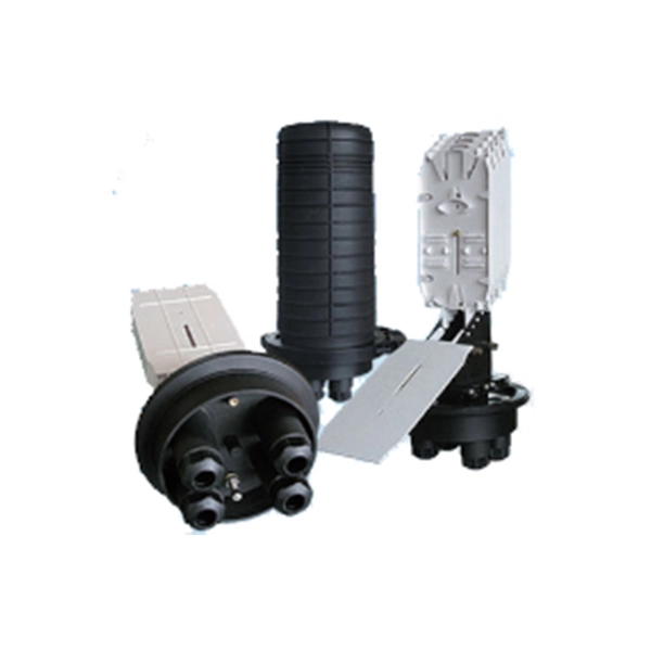
Learn how to install fiber splice trays inside an enclosure step by step. Quick, easy, and essential for fiber pigtail management! https://bit. Unlike fiber connectors, which can be plugged and unplugged, splicing creates a fixed connection that is typically more stable and has lower insertion. This document describes the installation of optical fiber with both single fiber and/or ribbon fiber splices into Optical Splice Enclosure (OSE) metal splice trays (Figure 1). Make sure you read and understand this instruction as well as instructions provided with related assemblies before. By following these detailed steps, the installation of your Fiber Splice Closure will be secure, organized, and maintained, ensuring high performance and longevity of your fiber optic network. Installing a fiber optic splice closure efficiently and effectively requires attention to detail and. How to install the splitter distribution box is the important information we need to know. This article includes the following: 1. Install the fixture 2. Box installation and fixed splitter distribution box 4. Install. Page 5 B (# 7 & 8) enter splice tray # 2. Route the fibers entering the splice tray up to splice point as shown. NOTE : Protection tube from side A enters splice tray from the far end as shown After splicing, close the splice tray and lock the front cover properly with the main and side lock.
[PDF]

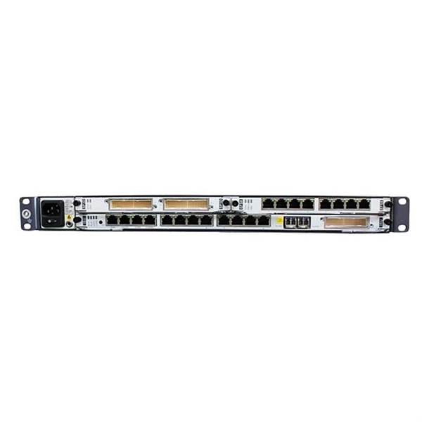
One SFP module is inserted into the switch's SFP port, and another module is inserted into the SFP port of the target device, facilitating data transmission through the fiber optic cable. SFP ports are small hot-pluggable module interfaces typically used for connecting fiber optics or copper cables. They support various transmission rates and distances, including 1G, 10G, and higher speeds. SFP modules can be selected based on the requirements, whether it's single-mode fiber for. An SFP port is a physically small slot in a networking device that accepts an SFP module insert. Most modern networking devices, such as Ethernet switches, servers, routers, network interface cards, and fiber media converters, generally have two or more built-in SFP ports. You may connect different. In plain terms, an SFP port on a gigabit switch is the little plug-in hole that gives the switch physical flexibility — the ability to use fiber one minute and copper the next without buying a different switch. Unlike fixed RJ45 copper ports, SFP ports support both fiber and copper modules, enabling far longer distances, greater flexibility, and improved scalability in enterprise. First, to connect SFP modules with fiber optic cables, ensure that the module type matches the line, as there are different modules for single-mode and multimode fiber. Next, insert the module firmly and securely into the SFP port, then attach the cable to the module using the connector. Switches with SFP ports can.
[PDF]
Single-mode optical splitters are optimized for single-mode optical fiber, while multimode optical splitters are tailored for use with multimode optical fiber. An Optical Splitter, also known as a beam splitter, is a passive optical device that divides a single input optical signal into two or more output signals. Conversely, it can also combine multiple signals into one. Its primary role is in Passive Optical Networks (PON), which are the foundation of. This guide demystifies fiber optic splitters, explaining their design, operating principles, types, key specifications, and real-world applications. It can distribute the optical energy transmitted through a single fiber to two or more fibers in a predetermined ratio or combine the optical energy from multiple fibers into one fiber. “Passive” means it needs no. You use optical couplers and splitters to split or join signals in fiber networks. For example, optical splitters send light to many output ports. This lets you connect more users to one network terminal. There are different types of fiber optic splitters available, with two of the most common being Fused Biconical Tapered (FBT) splitters and Planar Lightwave.
[PDF]

This article provides a detailed technical comparison between fiber optic and copper cables, offering a clear perspective for engineers, network architects, and procurement managers. The core distinction between the two technologies lies in the physics of data. However, the exponential growth in data demand has positioned fiber optic technology as the superior alternative for performance, scalability, and future-readiness., 10G/25G/40G/100G and beyond depending on optics and reach). Copper Ethernet scales too, but practical limits are lower and depend. The two main options are fiber optic cables and copper cables, each with its own advantages and drawbacks. Fiber optic cables are praised for their high performance and scalability, while copper cables remain a cost-effective choice, especially for budget-conscious projects and older systems. Copper wire is more susceptible to interference and has limited data capacity, making optical fiber the preferred choice for modern high-speed. Optical connectivity, utilizing fiber-optic technology, has emerged as the superior choice for modern networking, offering unparalleled performance, reliability, and scalability. For example, a typical 10 Gbps copper Ethernet link (such as Cat 6A) over 100 meters can consume approximately 5 to 8+.
[PDF]
For example, in a FTTH network, a single fiber from the telecom provider can serve 32 homes using a 1:32 splitter, eliminating the need for separate fibers to each residence. These unassuming devices enable a single optical signal to be divided into multiple paths, making them indispensable for sharing network resources efficiently—from residential FTTH (Fiber-to-the-Home) connections to large-scale telecom backbones. This guide demystifies fiber optic splitters. You use optical couplers and splitters to split or join signals in fiber networks. These devices help you control light signals well. For example, optical splitters send light to many output ports. It can divide the input optical signal into multiple output optical signals to meet the fiber optic access needs of multiple terminal devices. This type of device plays an important role in passive. A fiber-optic splitter, also known as a beam splitter, is based on a quartz substrate of an integrated waveguide optical power distribution device, similar to a coaxial cable transmission system. The optical network system uses an optical signal coupled to the branch distribution. The fiber optic. If you've ever wondered how a single fiber from your internet service provider can deliver service to an entire neighborhood or apartment building, you've wondered about the magic of optical splitters. The process of light beam splitting involves.
[PDF]
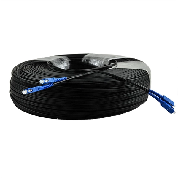
BiDi SFP+ changes the geometry: each module uses a single fiber pair directionally separated by wavelength, so you can run one strand where you previously needed two. One of the most common decisions network engineers face is selecting between single fiber SFP and dual fiber SFP modules. This comprehensive guide explores the differences between single and dual fiber SFPs, their respective benefits, limitations, and use cases—helping you make an informed choice. A single fiber SFP, also known as a BiDi SFP, is designed precisely for this purpose—enabling bidirectional data transmission over a single strand of optical fiber. Unlike traditional SFP transceivers that require two fibers—one for transmitting and one for receiving—a single fiber SFP uses. SFP (Small Form-factor Pluggable) is a compact, hot-pluggable network interface module used to connect network devices (switches, routers, firewalls) to fiber optic or copper cables. An SFP interface on networking hardware is a modular slot for a media-specific transceiver, such as for a fiber-optic cable or a copper. Both transmitting and receiving need one optical fiber to connect. Simplex SFP modules, also known as BIDI transceiver, employs a unidirectional transmission mechanism and have only one port. In practice, that means fewer splice points, smaller patch panels, and less conduit congestion—especially in retrofit buildings.
[PDF]
Picking up the best router for fiber internet isn't just about going to the market and choosing one of the best wireless routers. Instead, you need to carefully look at its specs, performance, and the type of securit.
[PDF]
A distribution box, also known as a fiber distribution hub or optical distribution box, is a larger enclosure designed to manage and distribute fiber optic cables to multiple endpoints. It serves as a central point for connecting and organizing numerous fiber optic. Although all three are related to fiber connection and management, their installation locations, functional roles, and positions within the network architecture are fundamentally different. Confusing these devices may lead to non-standard cabling at best, and serious challenges in network. In modern FTTH (Fiber to the Home) and optical communication networks, three types of fiber distribution products are widely used: Splitter Distribution Box, ODF (Optical Distribution Frame), and Fiber Terminal Box. The functions of the four connectors can be. First, let us learn the common point among ODF, fibre optic termination box and fiber optical distribution box, actually, they have similar function, we sort out them as following 4 aspects: 1. fiber termination and optical signal splitting 4. What is the difference between these fiber boxes.
[PDF]
Compared to conventional metallic cables, optical fiber provides an advantage of low loss (~ 0. 2dB/km) and wide bandwidth (several hundred MHz to THz) to enable long-distance, high-capacity communication. Fiber-optic communication is a form of optical communication for transmitting information from one place to another by sending pulses of infrared or visible light through an optical fiber. The light is a form of carrier wave that is modulated to carry information. Fiber is preferred. It was almost a century later before optical-based communication was put to practical use, thanks in large part to the invention of optical fiber and lasers. A laser's stable, highly directional beam of light (emitted from tiny semiconductor windows that measure just a few hundred thousandths of a. In 2020, we celebrated the 50th anniversary of the invention of low-loss optical fiber — an innovation that has transformed the way we connect and that lies at the cornerstone of our communications revolution. In a Corning lab on a Friday afternoon five decades ago, a single strand of glass and a. Fibre optics and optical communications is the use of thin strands of glass for sending information encoded into light over long distances. Total internal reflection prevents light inserted into one end of the fibre from escaping through the sides. Transferring information optically in this way.
[PDF]

The Cable Tray Sizing Calculator is an electrical calculator tool designed to determine the correct cable tray dimensions for electrical installations. Accurate fill ratio analysis and tray sizing per NEC, IEC 60364, and BS 7671 standards. Follow these simple steps: Define Tray Dimensions: Enter the width and depth of your planned cable tray (in mm or inches). Select Fill Standard: Choose 40% for power cables (NEC compliant) or 50% for. The all-in-one desktop software for cable tray sizing, fill rate analysis, bracket design, seismic verification, and thermal expansion calculations. Fully compliant with IEC, BS, NEC, VDE, and AREI standards. cable tray engineering. From initial sizing to final documentation — one tool handles it. Calculate cable tray fill ratio, weight loading, and derating factors for multi-standard compliance. This calculator features an interactive interface with advanced visualizations. Open the full calculator for the best experience. 0133 sq in each, the screen is about 0. This page is a preliminary cable-tray occupancy screen for early layout work. You need to install 50 power cables, each with a diameter of 0. The calculator would help determine if the chosen tray is sufficient or if a larger size is. Determine the total usable cross-sectional area of the cable tray by multiplying its width by its height (or depth). For mixed cables, sum the areas of all individual cables.
[PDF]
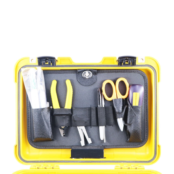
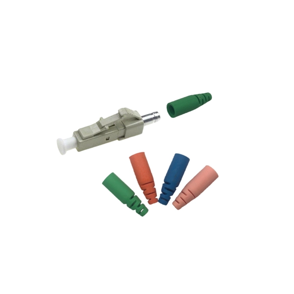
In this article, we will provide you with a step-by-step guide on how to install and remove fiber optic connectors properly. Step 1: Prepare the necessary tools and materials, including the fiber optic connector, cable stripper, fiber cleaver, and lint-free wipes. HomeNetworking is a place where anyone can ask for help with their home or small office network. No question is too small, but please be sure to read the rules before asking for help. We also welcome pretty much anything else related to small networks. I have this connector on my optic fibers cable. Terminating fiber optic cables essentially means putting connectors on fiber optic cable so that you can connect the cable to various devices or network components. Think of it as the equivalent of connecting the dots in a complex puzzle; without proper termination, the whole system can break down. The fiber optic tool kit contains tools to assemble SC connectors. Required consumables are sold separately. Consumables Kit: The consumables kits for single mode and multimode connectors are show below. If the connector is broken, it might need to be replaced rather than taken out. Removing these connectors requires care to avoid damaging the delicate fibers or the connector itself. Ensure that everything is clean.
[PDF]

Fiber optic adapters play a vital role in modern optical communication systems by enabling seamless connections between fiber optic cables. These small yet essential components ensure efficient data transmission, reduce signal loss, and maintain system integrity (1). In this article, we'll explore. Explore the essentials of fiber optic adapters, their types, benefits, selection, maintenance, and their role in future tech. They serve as interfaces for connecting fiber optic cables, facilitating. Fiber optic adapters are small but essential components that ensure precise alignment between connectors. Using the wrong type or neglecting cleaning can lead to signal loss and unstable connections., two fiber connectors) such that light can reliably pass from one to the other with minimal insertion loss and maximum return loss. Though fiber optic adapters are small accessories often ignored by technicians, they play a vital role in fiber telecommunications, connecting fiber optic cables and connectors. This article discusses their purposes, features, types, and how to choose and clean them. Most fiber optic connectors are composed of.
[PDF]
