Simply put, a relay is an electromechanical device that allows a high power load to be controlled with a low power circuit. The images below show a cross section of a relay very similar to what is on the RELAYpl.
[PDF]

This video provides a detailed walkthrough of designing and simulating an automatic light control system using Light-Dependent Resistor (LDR) and Triac in Proteus Software. Last updated on 13 August 2025 by Admin-Lavi Leave a Comment This article talks about Light Controlled Switch Circuit using IC LM311 and LDR. It simple and very useful and it feel light change near it. We find this circuit in many place like automatic light, street lamp and security system. Main. ABB's Control Room offering includes a comprehensive range of solutions designed to optimize the operator workspace for critical 24/7 processes across various industries. The project demonstrates how to create a smart lighting system that turns on/off automatically based. more This video. The Intro Screen changes as you play with it. It has a Play Area and a Control Area. A Construction Area creates a building space for components added from a Circuit Component Toolbox. Build and navigate your circuits there. If Voltmeters and Ammeters are out of the toolbox, you can take. Common sense schematics let you name a node "+5V" and know that the simulator will do the right thing automatically, keeping your schematics compact and elegant. This circuit activates or deactivates connected loads, such as LEDs or light bulbs, based on ambient light levels.
[PDF]

A relay protection tester is a core device used to verify the performance of relay protection devices. Its working principle can be summarized as “signal excitation – behavior detection. ”. It is divided into two parts: the main loop and the auxiliary loop. ” The tester has a built-in high-precision programmable power supply, capable of simulating various operating. When the transformer wiring type is Y/Y (Y0), the test wiring is very simple: when testing phase A, the tester IA is connected to the phase A of the high voltage side, and the tester IB is connected to the phase a of the low voltage side. After the neutral line of the high and low voltage sides is. Relay protection aids in detecting and preventing faults in electrical systems such as overcurrents or short circuits. As a core part of electric system reliability and safety, protective relays aid in preserving equipment and maintaining stability by isolating affected zones automatically via. THEY SHOULD BE GIVEN FIRST LINE MAINTENANCE ATTENTION. COMPREHENSIVE INSPECTION, MAINTENANCE AND TESTING PROGRAM. ” relay may only need to operate for 0. 15 seconds in its 30+ year life. But failure to operate as intended can result in extensive damage, extended power outages, and loss of life. NETA. Megger's smart relay testing solutions and expert support help you validate protection performance, improve system reliability, and ensure continuity of power across your network.
[PDF]
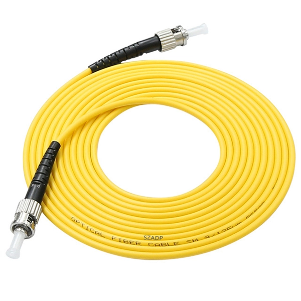
As a critical component in high-speed networks, fiber optic patch cords require micron-level precision. This guide unveils the complete production workflow compliant with **IEC 61754** and **Telcordia GR-326-CORE** standards, featuring proprietary quality control. If you've ever troubleshot a fiber optic network only to find that a microscopic dust particle caused the entire system failure, you understand why IPC-8497-1 exists. This standard represents the industry's collective wisdom on how to properly clean and assess contamination in optical assemblies. For harsh environments or other data center and IT networking applications where there is a greater risk of damage to your fiber optic network, armored fiber optic cables deliver the protection you require. Built with a steel-armored layer that provides extra crush and rodent resistance, these. Welcome to be our agent! Fiber optic patch cords, also known as fiber jumpers, are essential components in high-speed data transmission networks. Their performance directly impacts signal quality, insertion loss (IL), and return loss (RL). At ZION Communication, we design and manufacture a full range of fiber patch cords for: This guide will help you quickly understand the main types of. Ensuring the performance and reliability of fiber optic patch cords is fundamental to optical network integrity. 6-Step Manufacturing.
[PDF]

In this video, I'll show you how to build a simple and effective short circuit protection circuit using a relay. This DIY project is perfect for anyone looking to protect their electronics from accidental shorts. Last Updated on February 15, 2026 by Swagatam 117 Comments In this post I will try to explain the making of a simple 220 V, 120 V AC mains short circuit breaker using an SCR and a triac combination, (researched and designed by me). The circuit is an electronic version of the normal main circuit. One possible solution to the problem of overcurrent is to use a variable bench power supply with a current limit function. These power supplies allow You to set a current limit, preventing a high current flow when a mistake occurs. This circuit will. Why Publish? How to Make Short Circuit Protection Circuit: Hii friend, Today I am going to make a circuit for Short Circuit protection. This circuit we will make using 12V Relay. How this circuit will Work - when short circuit will occur on the load side then the circuit will be automatically cut o. In this tutorial, we will see how to make a short circuit protection using Relay. Many times accidentally terminals of batteries and other power supplies get short-circuited. Due to this, they get hot and start degrading. In the case of lithium-ion or lithium-polymer batteries, they may catch fire.
[PDF]
Home appliances TV sets, VCR, Microwave ovens Office machines Industrial equipment NC machines, Robots, Temperature controllers Photocopiers, Vending machines. Space saving design Wiring can be done with ease (DIN terminal). N.C. contact raw N.O. contact raw COM contact raw Coil terminal raw. N.C. contact raw N.O. contact raw COM contact raw Coil terminal raw. For Cautions for Use, see Relay Technical Information.
[PDF]

The IEEE standard for protection relays refers to a collection of guidelines developed by the Institute of Electrical and Electronics Engineers. These standards define the performance, accuracy, reliability, and testing requirements of protective relays used in electrical systems. Relay systems protect high-voltage equipment and transmission lines to ensure safe, stable systems. Although failure of a protective relay system may have severe local or regional impacts, most protective relay systems are not required to operate to prove they are in working order. Many of the protective relay systems are seldom called upon to work and have little means of proving they. The testing and verification of relay protection devices can be divided into four groups: Type tests are needed to prove that a protection relay meets the claimed specification and follows all relevant standards. Since the basic function of a protection relay is to correctly function under abnormal. Protective relays are decision-making elements in the protection scheme for electrical power systems. A strong test and maintenance program will keep protective relays in a high state of readiness and help utilities avoid equipment damage and prolonged downtime. This guide provides recommended. This utility standard establishes the requirements for testing and maintaining protection systems, automatic reclosing, and sudden pressure relaying.
[PDF]
Distance relays, also known as impedance relay, differ in principle from other forms of protection in that their performance is not governed by the magnitude of the current or voltage in the protected circuit but rather on the ratio of these two quantities.OverviewIn, a protective relay is a device designed to trip a when a is detected. The first protective relays were electromagnetic devices, relying on coils operating on moving par. Electromechanical protective relays operate by either, or. Unlike switching type electromechanical with fixed and usually ill-defined operating voltage thresholds. Electromechanical relays can be classified into several different types as follows: "Armature"-type relays have a pivoted lever supported on a hinge or knife-edge pivot, which carries a moving contact. These relays may.
[PDF]
Protective systems in electricity delivery networks have a major role to play in the increasing of renewable energy systems, and a broad understanding of their current a future application can aid into better tak.
[PDF]
Relay protection is the discipline of designing schemes that detect faults, coordinate relays, and isolate equipment without outages. It emphasizes selectivity, coordination, fault response, and system behavior rather than individual relay devices. Relay protection is often misunderstood as a. A protective relay is an intelligent electrical device designed to detect faults in power systems and initiate corrective actions such as tripping a circuit breaker. : 4 The first protective relays were electromagnetic. This document provides recommendations, background and philosophy on relay protection that is not available in M07. The facilities to which this Document applies are generally comprised of the fol-lowing: In analyzing the relaying practices to meet the broad objectives set forth, consideration must. What is a Protective Relay? A protective relay is an intelligent device that senses abnormal electrical conditions, such as overcurrent, under-voltage, or frequency deviations. It initiates the operation of circuit breakers to isolate the affected section. This prevents damage to equipment, reduces. Protective relays and devices have been developed over 100 years ago to provide “lastline”of defense for the electrical systems. They are intended to quickly identify a fault and isolate it so the balance of the system continue to run under normal conditions. The selection and applications of.
[PDF]

Review cutout sizes and modules. See specs, datasheets, order online. Vertical Distribution Managers are available in 8” and 12” widths. The VDM offers quick and easy cable routing for high density cable installation. Optional dual front doors offer easy access to cables and provide an elegant look for your data center. Cable fingers and spools support cables as they. Cable entry frames and kits for enclosures, panels simplify routing and strain relief. 91 inches in height and intended for use with 42U relay racks. It is used to organize cables on a relay rack which helps maintain proper airflow. Forward facing and equipped with a hinged front cover, it makes cable access quick and easy. The manager can also be. The M Series has been specifically designed to meet the demanding & varied requirements for protection relay applications in power utility sub-station environments. The standard 4U high 19-inch rack mounting modular configuration simplifies panel design & installation. Mounting points & overall. Weight capacity: 2,000lb. K04. Rackmount Mart - Rackmount Chassis and Rackmount LCD Source. Provide rackmount chassis, rackmount, rackmount lcd, rackmount monitor, kvm switch, disk array, single board computer, industrial computer, mobile rack, server rack, power supply, server case, raid tower, pc case, accessory, cabinet server.
[PDF]
This article covers various types of protective relays, such as overcurrent, directional, and differential relays, highlighting their operating characteristics and applications in electrical systems. Different Types of Protective Relays What is a Protective Relay?. Protective relays and devices have been developed over 100 years ago to provide “lastline”of defense for the electrical systems. They are intended to quickly identify a fault and isolate it so the balance of the system continue to run under normal conditions. The selection and applications of. Protective Relay Definition: A protective relay is an automatic device that senses abnormal conditions in electrical circuits and triggers actions to isolate faults. Types of Protective Relays: Protective relays are categorized by their mechanism (electromagnetic, static, mechanical) and function. A protective relay is an intelligent electrical device designed to detect faults in power systems and initiate corrective actions such as tripping a circuit breaker. : 4 The first protective relays were electromagnetic devices, relying on coils operating on moving parts to provide detection of abnormal operating conditions such as. Relion protection and control relays for several application reduce complexity.
[PDF]
The K factor (or zero-sequence compensation factor) adjusts the measured impedance for the phase-to-ground fault loop by accounting for the contribution of zero-sequence currents. This compensation is critical because zero-sequence current introduces an offset in the fault impedance. The protection and control devices in electrical equipment can be referred to by numbers, with appropriate suffix letters when necessary, according to the functions they perform. These numbers are based on a system that is adopted by a standard for automatic switchgear by Institute of Electrical. The following Terms are used in protective relaying: 1. Fault Clearing Time 5. Drop Out or Reset value 8. Sealing Relay or holding Relay 10. Time-graded protection is implemented using overcurrent relays with either definite time characteristic or inverse time characteristic. The operating time of definite time relays does not depend on the magnitude of the fault cur-rent, while the operating time of inverse time relays is shorter the. Displaying title 47, up to date as of 5/06/2026. Title 47 was last amended 4/30/2026. There have been changes in the last two weeks to Part 90. Without proper. Also principles of various protective relays and schemes including special protection schemes like differential, restricted, directional and distance relays are explained with sketches. The norms of protection of generators, transformers, lines and capacitor banks are also given. The procedures of.
[PDF]


