This paper presents a set of newly developed modeling, simulation and testing tools aimed at better understanding the design concept and related applications for protective relaying and substation automation solutions for the smart grid. presentation of protection and control relaying. The report will identify methodology behind these practices, present issues raised by the integration of microprocessor relays and the internal logic and external communication configurations, ying. At Keentel Engineering, we specialize in modeling, simulating, and deploying advanced protective relays to ensure the robustness of medium-voltage (MV) and high-voltage (HV) networks. Our engineering services help utilities, OEMs, and renewable developers simulate real-world contingencies and. This Modern Power System Protective Relaying training course has been designed to provide a clear and perfect understanding of power system protection schemes and devices, including protection relays, fuses, circuit breakers, and other protective devices. In modern power systems, nowadays. To ensure that protective relays, circuit breakers, and other protection devices correctly and selectively isolate faults, minimizing damage to equipment and interruptions to customers while maintaining system stability. One-line diagrams and detailed network data (lines, transformers, buses).
[PDF]
of relay protection coordination for a PV power plant connected to the distribution network is presented. In recent years, installation of PV power plants in the distribution network has increased significantly. I.
[PDF]
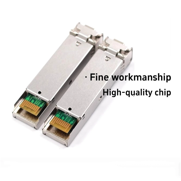
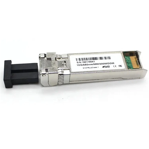
Commonly, a power meter on its own is used to measure absolute optical power, or used with a matched light source to measure loss. When combined with a light source, the instrument is called an Optical Loss Test Set, or OLTS, typically used to measure optical power and end-to-end optical loss.OverviewAn optical power meter (OPM) is a device used to measure the power in an signal. The term usually refers to a device for testing average power in systems. Other general purpose light power measuring. The major types are (Si), (Ge) and (InGaAs). Additionally, these may be used with attenuating elements for high optical power testing, or wavelengt. A typical OPM is linear from about 0 dBm (1 milli Watt) to about -50 dBm (10 nano Watt), although the display range may be larger. Above 0 dBm is considered "high power", and specially adapted units may measure u.
[PDF]

Explore a comprehensive guide to residential electric meter box wiring diagrams, offering clear instructions for safe and efficient installation. A distribution box is the heart of any electrical system. It takes the incoming power and safely distributes it to different circuits throughout your building. However, the key to. Learn how to wire a distribution box step by step! This video shows real on-site footage of electrical installation, demonstrating safe and standardized wiring methods used by professionals. It has three categories: residential, commercial and industrial electrical distribution boxes, all of which play important roles in their respective electrical. Cleaning of the various PXBCM device housings should only be done with power and mains disconnected. A clean dry rag can be used to remove dust. No liquids should be used. Catalog Numbers Catalog Number DescriptionSuffix De- scription Notes PXBCM-MB Meter Base PXBCM-MMS-L09-A Meter Module Strip. full turn-key system solution backed with industry leading reliability and performance. Applications - The minimally invasive retrofit kit enables the opportunity existing remote power infrastructure cross arm, & wiring) providing the total cost of ownership. Failure to strictly adhere to the.
[PDF]
The high-voltage SiC MOSFET power modules enable high-frequency and high-efficiency power conversion. The parasitic inductances induced by traditional packages of this device technology significantly d.
[PDF]
The ring main circuit is commonly used for powering lighting circuits and plug sockets in residential and commercial buildings. It provides a safe and reliable method of electrical distribution, ensuring a consistent supply of power to each outlet. WATERPROOF DISTRIBUTION BOX: The power socket distribution box is made of high-quality ABS plastic material, with a size of 9. The waterproof grade of the shell is IP65. It is equipped with 4 IP44 waterproof sockets., can. The distribution box (DB box) helps safely and efficiently distribute electrical power. Today, electrical systems are essential for homes and industries. But what exactly is a power distribution box, and why is it so essential in our daily lives? The DB panel board controls the flow of electricity. Also known as a distribution board or breaker panel, it acts as the control hub, distributing power to different circuits and protecting them from overloads and faults. Here, we'll delve into what an electrical distribution box is, how it. Portable distribution boxes are mainly composed of core components such as shells, circuit breakers, sockets, terminals, leakage protectors, fuses, etc. As a protective "armor", the shell is mostly made of high-strength engineering plastics or aluminum alloys. Understanding the ring main circuit diagram is essential for electricians and individuals involved in electrical installations and repairs. The ring main circuit consists of a loop of cable, which.
[PDF]

This guide covers the critical steps, from selecting the right electrical cable tray and performing accurate cable fill calculations to managing a safe cable pull through and ensuring all bonding and grounding requirements are met. Article Summary: A compliant cable tray installation requires a thorough understanding of NEC Article 392, proper structural support, and precise installation techniques. Structural building members should never be cut, and cable trays should not be installed in hoist ways or where subject to physical damage. Cable tray systems re to be installed so that they are accessible. Here is a step-by-step guide on how to install a standard metal cable tray system (e., ladder or perforated type). But before you lay the first tray or clamp down a single cable, you need a solid plan. When ofloading tray from a flat deck trailer using an overhead crane, care should be exercised in the placement and length of the slings to prevent crushing the product (siderails). Only ofload. Cable tray systems are designed for easy installation and to accommodate power, communications, and signal cabling across a variety of applications. When properly installed, cable trays prevent damage to cabling and the area's structural integrity. When installed and engineered properly, cable.
[PDF]
In this video, we'll walk you through the process of wiring a home distribution box with a detailed connection diagram. Whether you're an electrician or a DIY enthusiast, this guide will help you understand the basics of home electrical distribution. more Welcome to our channel! In this video. This guide provides step-by-step instructions for connecting a distribution box and highlights key factors to consider during installation. What Is a Distribution Box? A distribution box, also known as an electrical distribution board, is a critical component in electrical systems. It has three categories: residential, commercial and industrial electrical distribution boxes, all of which play important roles in their respective electrical. Understanding how to safely set up the main connections of a home's power distribution system is essential for ensuring reliable and secure operation. A correct installation process minimizes the risk of electrical faults and increases the longevity of your setup. It is usually equipped with circuit breakers, fuses, terminal connectors, and other components. It serves as a central hub for distributing electricity throughout a building, ensuring that power is delivered safely and efficiently to all the required locations.
[PDF]

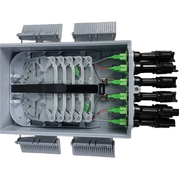
Specialized Products offers LED and laser fiber optic light sources from AFL, EXFO, VIAVI, Photonix, Tempo Communications and other leading brands. Our selection includes multimode, single mode and quad light sources, with FC, LC, SC, ST connectors and. The state, throughput, and identification of an optical fiber can be easily checked with fiber testers by coupling highly visible laser light into the optical fiber. The red light of a laser is coupled into the core of an optical fiber in a targeted manner (an LED is usually too weak a source to be. Definition: delivery of power for electronic devices via light in an optical fiber which is converted to electricity Alternative terms: power-over-fiber, photonic power Category: fiber optics and waveguides Related: fibers fiber cables laser diodes fiber optics Page views in 12 months: 3730 DOI:. Prizmatix Silver-LED fiber-coupled LEDs provide high power continuous (CW) low noise output as well as fast pulsed operation from optical fiber. Silver-LEDs are available at deep UV, UV, Violet, Blue, Green, Yellow, Red or NIR. Fiber Coupled LED light source modules are ideal for use with high NA. This paper discusses the application of fibre optic technology and its benefits in the operation of solar power plant. Fibre optic technology enhances solar power plant operations, ensuring reliable data transmission and control.
[PDF]
The following tutorial explains how to wire split-phase (240V single-phase) circuit breakers and load points in a residential distribution panel. A distribution box is the heart of any electrical system. It takes the incoming power and safely distributes it to different circuits throughout your building. Whether in a home or an industrial facility, this box keeps your electrical setup organized, functional, and efficient. However, the key to. Household distribution boxes are essential components in modern electrical systems, providing a centralized location for managing electrical circuits within a home. While many families are familiar with these boxes, there is often a lack of understanding regarding their specifications and proper. While overhead lines have been ordinarily considered to be less expensive and easier to maintain, developments in underground cables and construction practices have narrowed the cost gap to the point where such systems are competitive in urban and suburban residential installations, which. Understanding how to safely set up the main connections of a home's power distribution system is essential for ensuring reliable and secure operation. Proper knowledge is crucial for. To install a whole-home backup power system, start by evaluating your home's power needs and choosing the right backup solution. Let's explore how these critical components work and why they deserve your attention.
[PDF]
Access 61 verified Power Distribution Unit,distribution Box buyers in Venezuela with contact details, shipment history, import pricing & supplier data. Updated through Jan 2026. Machinesequipments is a Power Distribution Equipment Manufacturers in Venezuela, Power Distribution Equipment Venezuela, Power Distribution Equipment Suppliers Venezuela and Exporters in Venezuela for Power Distribution Equipment. You can contact us by email at sales@machinesequipments. THUNDERNET C A accounted for 21% of Venezuela's total imports with (8 shipments). LANLY LATAM. If you are searching for Power Distribution Panel in Venezuela, Brilltech Engineers Pvt. We have a well-equipped manufacturing unit with all the advanced resources to cater to your distinct requirements as per your industry preferences. Being one of the. AMETEK Land (Land Instruments) is the world's leading manufacturer of monitors and analysers for industrial infrared non-contact temperature measurement, combustion efficiency and environmental pollutant emissions. Through our trusted range of. We've been engaged in serving our comprehensive and customized range to customers around the globe. Our complete ranged is manufactured at our in-house. Brilltech Engineers Pvt. Moreover, our focus on maintaining high quality and attaining customer satisfaction stands us ahead of the.
[PDF]
In 1948 and 1954, several companies formed the Cooperación Venezolana de Fomento (CVF) to connect the isolated regional and local power grids with a network of 115 kV power lines.OverviewThe electricity sector in Venezuela is heavily dependent on, with this energy source. Generation of electricity started end of the 19th century by the construction of small-scale hydroelectric power plants. In the first half of the 20th century, the electricity sector was in hands of private companies, which built. The electricity sector in Venezuela is heavily dependent on hydroelectricity, which accounted for 64% of the nation's electricity generation in 2021. Besides hydroelectric power, Venezuela also relies on. The largest power companies are state-owned CVG Electrificación del Caroní [] (EDELCA), a subsidiary of the mining company, and Compania Anonima de Adminis.
[PDF]
An optical power meter (OPM) is a device used to measure the power in an signal. The term usually refers to a device for testing average power in systems. Other general purpose light power measuring devices are usually called,, power meters (can be sensors or ), or lux meters. A typical optical power meter consists of a , measuring and display. The sens.
[PDF]