The National Electrical Code (NEC) does not specify the maximum distance for a ground rod from a panel. However, the ground rod should be placed as close as possible to the panel to ensure an effective ground connection. Electrical clearances set the minimum safe distances for panels, overhead lines, pools, and buried wiring — and ignoring them has real consequences. (If these areas are accessible to other than pedestrian traffic, then one of the other conditions applies). Above finished grade or sidewalks, or from any platform or projection from which they. Learn key electrical code requirements for junction boxes, including sizing, grounding, materials, and clearance to ensure safety and efficiency. Whether it's a. The National Electrical Code (NEC) provides comprehensive safety standards for electrical installations, including requirements for electrical panels (main service panels and subpanels or breaker box). NEC Article 408 covers switchboards, switchgear, and Panelboards installation and applications. Following the manufacturer's installation instructions for the ground rod and.
[PDF]
This section applies to grounding of transmission and distribution lines and equipment for the purpose of protecting employees. Note to paragraph (a): This section covers. Correct grounding of services depends upon understanding the definition and role of the grounded conductor. The neutral conductor is typically the grounded conductor connected to the system's neutral point, carrying current under normal operation. Grounding electrode conductors must be connected at. Learn the grounding and bonding rules when powering two or more buildings or structures in the same area with a single service. To catch up on Lorenzo Mari's series on National Electrical Code 2023 Basics: Grounding and Bonding, follow these links: NEC's Section 250. Bonding is connecting things together with a conductive path to establish electrical continuity. Both are foundational safety concepts in the NEC, and. NFPA 70: National Electrical Code Article 250 covers the minimum requirements for grounding and bonding and, although the NEC lists requirements to abide by, it should not be taken as a design manual. Some terms and requirements discussed may be true for the European standards, however, the intent.
[PDF]
In this video, we'll walk you through the process of wiring a home distribution box with a detailed connection diagram. Whether you're an electrician or a DIY enthusiast, this guide will help you understand the basics of home electrical distribution. more Welcome to our channel! In this video. An electrical panel box, also known as a breaker box or a distribution board, is a crucial component of any electrical system. It serves as a central hub for distributing electricity throughout a building, ensuring that power is delivered safely and efficiently to all the required locations. What is Distribution Board? Distribution board. Hey, in this article we are going to see the Single Phase Distribution Box Wiring Diagram and Connection Procedure. And all the switching and protective devices are installed in the. Are you ready to master the skill of building electrical panels? This detailed guide provides an excellent base for beginners. Learn about the essential components of panels, such as the circuit breakers and fuses that safeguard against hazards. Then, delve into complex wiring configurations. Single Phase wiring installation is the most common wiring in residential buildings. In Single Phase supply (230V in UK, EU and 120V & 240V in the US & Canada), there are two (one is Line (aka Phase, Hot or Live) and the other one is Neutral) incoming cables from the utility poles to the kWh energy.
[PDF]

Run a ground wire from your metal patch panel rack to the grounding bar, use grounding lugs on the rack. Probably not necessary, but use Noalox between the lug and the rack. Remove paint if you want to go all in. Install and ground coax grounding blocks for your antenna. A Cat6 shielded patch panel is a modular component that connects and organizes multiple Ethernet cables in a central location. Unlike unshielded panels, shielded patch panels feature a conductive metal body and a grounding terminal to block EMI and maintain network integrity. GYA's shielded patch. A patch panel is a hardware device used to organize and manage network cable connections, helping to keep network wiring neat and efficient. Based on the shielding type, Cat6 copper patch panels are categorized into two types: shielded and unshielded. The rack itself is then bonded to the Secondary Busbar (SBB) of the telecommunications room. This. Correct STP grounding turns shielding into real EMI protection. This guide shows how to maintain drain‑wire continuity, bond safely at the equipment side, avoid ground loops, and validate results with simple tests. Cabling is cat5e UTP for data and phone. Coax is RG6 with 2 seperate runs, one for commercial tv provider, other for an attic mounted antenna that I'd like to eventually move to the roof. Is there a requirement (USA NEC) to.
[PDF]

Attach a ground wire from one of the threaded studs (A) at the bottom of the housing, to the mounting plate (B). The ground resistance between all system parts shall be <. The correct connection method of Distribution box grounding wire mainly includes the following steps: 1. This position is the connection point of the grounding wire in the. The National Electrical Code (NEC) lists eight specific methods to make grounding and bonding connections in Sec. Failure to install these connections properly can result in shock, fire, or, most certainly, power quality problems. Let's take a look at each one in more detail. Listed pressure. Make the most of outdoor spaces with permanent, weathersafe power. Learn our complete installation process from start to finish. Watch our video to learn more. Securing the ground wire: Secure the grounding wire to the ground bar using a grounding screw or terminal. Each DISTRIBUTION BOX and controller must be grounded. On the US market, a 5. 26 mm 2 (10 AWG) ground wire must be used, and in all other markets a 6 mm 2 must be used. Grounding of the units: Attach a ground wire from one of. Learn how to install a distribution box safely and correctly. Covers wiring, placement, standards, and expert tips for a compliant setup. A distribution box is the heart of any electrical system. It takes the incoming power and safely distributes it to different circuits throughout your building.
[PDF]

Lighting Circuits: Use 1. 5 mm² copper wire. Dedicated Circuits: AC, geysers, and ovens should have 4. Main Incoming Cable: Use 10 mm² or 16 mm² for main supply connections. Also, consider. Professional electrical wire sizing tool based on National Electrical Code (NEC) standards. Calculate proper wire gauge, voltage drop, and ampacity for safe electrical installations. Input your electrical parameters to get accurate wire size. Comprehensive NEC-compliant electrical feeder size charts with copper and aluminum ampacity tables, voltage drop calculations, and real-world installation examples for safe electrical work. Electrical feeder sizing is one of the most critical calculations in any electrical installation, yet it's. This guide gives a clear tech look at home wiring sizes – breaking down what matters without fluff or filler. We'll show you clear, useful info and steps that make sense when setting up your setup. What is House Wiring Cable and Why Does It Matter So Much? Simply put, a house wiring cable is the. Choosing the right wire size is critical for electrical safety and code compliance. Whether you're building a new home, remodeling, or adding circuits, properly sized cables protect against overheating, voltage drop, and fire hazards. Incorrect sizing not.
[PDF]
In this guide, we'll break down the key wiring layout, main control panel components, and how everything connects — from the main power isolator to the PLC and sensors on the production line. Every roll forming machine relies on a precisely designed electrical control and wiring system. This system ensures that motors, sensors, drives, and. This guide will walk through the key points you need to consider when preparing electrical schematics and wiring diagrams for a roll forming machine. This guide breaks down the entire electrical system of a modern roll forming machine — from incoming 3-phase supply to flying shear synchronization — with: A complete roll forming electrical system contains: Roll forming machines are typically built for: Voltage mismatch damages VFDs, transformers. Electrical design is the backbone of any roll forming line. Electrical design is the backbone of any roll forming line. These machines convert metal coil.
[PDF]

The easiest way is to use the $3 "spec-grade" receptacles which come in a box instead of loose in a bin. If it's just black and white wires with a cloth or plastic covering and no ground wire you'd need a retroit grounding wire to have grounded outlets. A clearer picture of the cable entering will help. Can you post photos that show clearly where the cables enter the box at, please? @Traveler No!. The process of wiring a small breaker box, often called a subpanel, is a common task when adding power to a detached structure like a shed, garage, or a major home addition. These smaller distribution centers are designed to take power from a larger main service panel and distribute it locally to. How do I wire a mini circuit breaker distribution box that doesn't have bus bars? I have a circuit going to my shed from my house and I want to have two separate breakers inside the shed (one for outlets, one for other stuff) so I bought this from amazon (Amazon. com: 2 Way Distribution Box Circuit. In this video, we'll walk you through the process of wiring a home distribution box with a detailed connection diagram. more Welcome to our channel! In this video. Connecting a distribution box involves several steps to ensure proper electrical flow. But first, the rules: Turn off the power when working with electricity. Make sure the power's off using a non-contact voltage tester or multimeter. One final tip: Get into the habit of making connections in this.
[PDF]
This video shows real on-site footage of electrical installation, demonstrating safe and standardized wiring methods used by professionals. more Learn how to wire a distribution box step by step! This video shows real on-site footage of. A distribution box is the heart of any electrical system. It takes the incoming power and safely distributes it to different circuits throughout your building. Whether in a home or an industrial facility, this box keeps your electrical setup organized, functional, and efficient. However, the key to. In this video, we'll walk you through the process of wiring a home distribution box with a detailed connection diagram. What is Distribution Board? Distribution board. An electrical panel box, also known as a breaker box or a distribution board, is a crucial component of any electrical system. It serves as a central hub for distributing electricity throughout a building, ensuring that power is delivered safely and efficiently to all the required locations. A distribution board (also known as a service panel or breaker box) is a centralized collection of circuit breakers, fuses, and/or relays used to control and protect the wiring in a home. The diagram. Electrical wiring powers everything in your home, from lights and outlets to major appliances. We'll break down the key parts of a home.
[PDF]
Finding the best electrical boxes for your home renovation or redo is vital. The right material, type, and size can increase security while eliminating the risk associated with house fires due to short circuit pr.
[PDF]

There are two electrical terminals, X and Y, where your cables must be connected. In this case, X refers to Black while Y refers to White. You need to connect X and Y with hot and neutral wires respectively. This is the most essential step. Each hot wire is 120 to 240 volts from the. Fortunately, anyone that understands color codes and electrical wiring, in general, can use X and Y wires and terminals. Circuits typically run on three wires. The hot wire brings power from the panel. In a standard setup, X and Y terminals typically correspond to specific colors: black for X and red for Y in 240V systems. Knowing these codes helps you properly connect circuits, ensuring. The standard electrical wire color code mandated by the National Electrical Code (NEC) is a critical safety system for licensed electricians. For typical building AC circuits (commonly up to 600 volts nominal), the NEC specifies identification rules for grounded conductors (neutral), requirements. Wires in electrical typically have color-coded labels., the National Electrical Code (NEC) defines required colors for neutral and grounding conductors, while hot wire colors often follow industry convention rather than strict rules. The table below gives a quick snapshot of the most common electrical wire colors you can see at home.
[PDF]

Ask This Old House master electrician Heath Eastman explains the uses and purposes of different types of electrical boxes. Selecting the right electrical box for your project can be confusing because of the many options available. Circuit breaker boxes – also known as breaker panels or main breaker panels – keep the lights on, electronic devices powered up and the refrigerator running. They host circuit breakers designed to safely distribute the correct amount of electricity to every room and outlet in your home. Whether you're starting new construction or adding to existing. Electrical boxes, also known as junction boxes or outlet boxes, are enclosures that house electrical connections, switches, and outlets. Whether you're a homeowner planning a renovation or a curious mind eager to understand the backbone of modern living, our expert residential electrician insights will illuminate every twist, turn, and wire connection, ensuring your home remains both functional and safe. What is Electrical Wiring?. Electrical panel replacement costs range from $518 to $2,188, and your total reaches up to $4,500. The amperage your home needs and the type of panel you choose will determine your final project cost for the replacement. You should budget for permits, drywall repairs, and wiring upgrades so your.
[PDF]
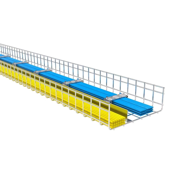
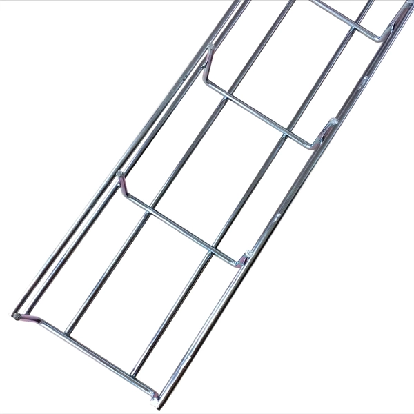
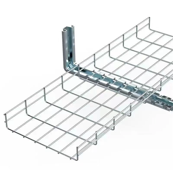
Standard splice plates can often provide a safe electrical path if they are UL Classified and bolted tight. However, you must use copper bonding jumpers if the tray is painted or has expansion joints for movement. A. The intent of this article is to review grounding practices for cable tray wiring systems. The Equipment Grounding Conductor is the electrical circuit's safety conductor. When designing a cable tray. Snap Track requires only single bonding jumper. Installation Guideline: Scroll to bottom of page to view All Bonding Jumpers Cut Sheets A bonding jumper is required to be installed with adjustable splices and expansion splices. If an EGC cable is installed in or on a cable tray, it should be bonded to each or alternate cable tray sections via grounding clamps (this is not required by the NEC® but it is a desirable practice). In addition to providing an. Do I have to use a bonding jumper at each cable tray splice point that is bolted tightly together? I currently have 3 runs of 24 tray about 80ft long. we have one expansion plate section per run in which I plan on using a bonding jumper at, I am curious about all other points You aren't even. Wire mesh cable trays are widely used in commercial offices, industrial facilities, data centers, and smart building infrastructure because they provide unmatched flexibility, excellent airflow, and fast, adaptable installation. Their open-grid design makes it easy to route, add, or modify cabling.
[PDF]