
This paper will review the development of fiber-optic high-temperature sensors over the last 30 years, presenting their design and fabrication methods according to sensing type and typical temperature measurement performance. The full paper consists of eight sections. Fiber-optic high-temperature sensors are gradually replacing traditional electronic sensors due to their small size, resistance to electromagnetic interference, remote detection, multiplexing, and distributed measurement advantages. This paper reviews the sensing principle, structural design, and. Luna's Optical Backscatter Reflectometer (OBR) products are based on OFDR and provide a level of detail and precision not available with the prevailing fiber optic diagnostic tool - the optical time domain reflectometer (OTDR). OBR systems map out loss along a single-mode fiber (SMF) or multi-mode. breadth and most comprehensive solutions for optical communications test products to be found in one place. Corning's High Temperature Fibers are designed for applications requiring improved fatigue resistance, high usable strength, and excellent resistance to higher temperatures and hydrogen permeation. Thus, wireless communication -situ processing of data would combined with in significantly improve the ability to include sensors into high temperature systems and thus lead toward more intelligent engine systems. NASA Glenn Research Center (GRC) is presently lea, communication systems,ding the.
[PDF]
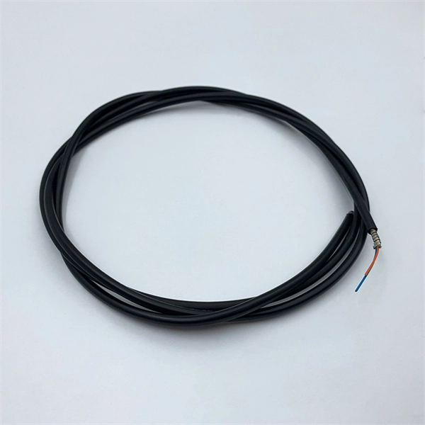
The zero-buoyancy rov cable was born as a power connection and control of underwater robot equipment, as well as signal transmission and feedback link cable applications. The zero-buoyancy cable has been tested by the market and practice due to its excellent. The global underwater zero buoyancy cable market is experiencing robust growth, driven by the expanding offshore energy sector, increasing demand for subsea infrastructure development, and advancements in underwater communication technologies. Linden Photonics is renowned for its innovative fiber-optic solutions, specifically designed for Remote Operated Vehicles (ROVs). These ROV tethers are crucial in underwater applications, offering high performance, durability, and reliability in challenging environments. For use with ROV's (Remote.. Customizable neutral buoyancy fiber optic power cable for ROVs and underwater drones. High‑performance hybrid design combining power and data in one composite cable. Engineered for seawater resistance, flexibility and subsea reliability. Suitable for inspection systems, subsea cameras and. At Invocean, we understand the increasing demands and the critical nature of Remotely Operated Vehicles (ROVs) in various industries such as underwater construction, surveillance, salvage, and scientific research. To support these high-performance tasks, ROVs and Micro-ROV's require reliable.
[PDF]

Telescopic mast system with advanced vibration-dampening technology to minimize jitter and ensure stable communication and data transmission, even in the most demanding terrain and vehicle movements. Fireco designs and manufactures the most comprehensive line of standard and custom telescopic masts using high quality materials with industry leading engineering and quality testing practices to provide our customers with the world's best mobile masts. Will-Burt's telescopic masts and tower systems provide intelligent. Telescopic mast systems play a critical role in modern field operations—enabling elevation of cameras, antennas, lights, sensors, and communication gear in demanding environments. Whether for surveillance, broadcasting, defense, or emergency response, choosing the right mast system ensures reliable. Floatograph, along with its utility industry partner, Eversource Energy, developed the Rapid Pole® – Temporary Power Pole system to reduce customer downtime, allowing crews to re-energize a circuit in as little as 20 minutes. Floatograph's masts come in height options from 10 to 100 feet, and are. Advanced telescopic mast solutions designed for versatility in the field, providing crucial support for on-the-move (OTM) missions. Erecting the Telescoping Mast is made by simply connecting guys and brackets to the attached unique heavy duty rolled edge guy rings and clamps, extend the sections, insert the locking cotter pins, rotating the tubes to.
[PDF]

Solution: To solve this problem, you can follow these steps: Check if the fiber and optical modules are compatible. A switch must use optical or copper modules that have been certified for use on Huawei switches. Huawei is not liable for any problem caused by the use of non-certified optical or copper. This article summarizes several solutions for using optical modules with switches and common problems encountered during usage, along with specific solutions. Huawei S5720-32P-EI-AC Switch II. During use, reading optical module information helps understand its real-time operating status, enabling faster troubleshooting of link abnormalities. The following uses the. ers, only the short transmission distance is supported. Whether optical attenuators need to be deployed at the receive end o. A leaf-spine refresh can fail in subtle ways: a port locks in an unexpected speed, optics negotiate but traffic stays dark, or DOM readings mismatch. This case study helps network engineers and field technicians validate a Huawei CloudEngine transceiver against switch requirements before rollout.
[PDF]

A passive optical network (PON) is a fiber-optic telecommunications network that uses only unpowered devices to carry signals, as opposed to electronic equipment. In practice, PONs are typically used for the last mile between Internet service providers (ISP) and their customers. In this use, a PON. Passive Optical Networks (PON) have emerged as a leading solution to meet these demands, offering high bandwidth, scalability, and cost-effective deployment. This comprehensive guide delves into the world of PON, exploring its various types, benefits, and applications, particularly in Fiber to the. Optical splitters are used to split the signal into multiple branches. There could be several levels of splitters, which are separating the outside plant into different sections: fiber feeder, distribution, drop. Its principle—distributing the signal from a central point to numerous subscribers via entirely passive splitters—has revolutionized the economics of access networks. This makes it a cost-effective and reliable solution for.
[PDF]

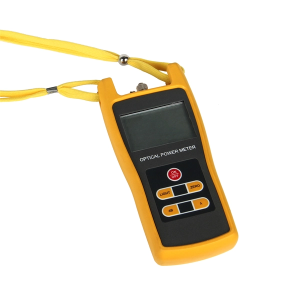
Managing optical attenuation helps keep your signal safe. Clean your optical connectors so you do not lose. Optical Signal Attenuation is the single greatest factor limiting the distance and performance of your network. Understanding it is crucial for anyone involved in data centers, telecommunications, or enterprise networking. This guide will demystify signal loss, explore its causes, and show you how. In high-speed environments, where the optical link budget is measured in fractions of a decibel, diagnosing and eliminating unexpected loss is the network engineer's most critical task. This field guide provides a systematic, step-by-step approach to troubleshooting and resolving the most common. Signal loss in Fiber Optic networks can make data slow. It can also break your connection. You should fix it fast to get speed and stability back. > You can solve this with simple steps. Signal Degradation (Loss of Light) When the signal quality degrades, it could be a sign of attenuation or excessive loss in the system. The signal might become weaker, resulting in slower speeds or dropped connections. -. Fiber optic networks are celebrated for their speed and reliability, but even the best systems can encounter problems. When issues like signal loss, slow speeds, or intermittent connectivity arise, systematic troubleshooting is key. Things like impurities in the fiber core and reflections at the core-cladding edge cause this drop.
[PDF]
It provides a general plan for spectrum use and the basic structure to ensure efficient use of the spectrum and the prevention of radio frequency interference between services. Learn about the market conditions, opportunities, regulations, and business conditions in tajikistan, prepared by at U. Embassies worldwide by Commerce Department, State Department and other U. agencies' professionals Information and Communication Technologies (ICT) Tajikistan's ICT sector is. Satellite Internet Market Growth The global satellite internet market is experiencing steady growth, driven by increasing demand for reliable connectivity in remote and underserved areas. Through use of the table, manufacturers will have a guide to where in the spectrum to design and build equipment, and. Ministry of communications of Republic of Tajikistan We have an excellent working relationship with the Tajikistan Telecom Wireless Regulatory Authority, officials at Ministry of communications of Republic of Tajikistan. This means that we can ensure all your applications for Wireless Regulatory. On 7 April 2025, in Dushanbe (Tajikistan), Intersputnik, at the invitation of the Communication Service under the Government of the Republic of Tajikistan, attended the International Forum “Digital Transformation: Prospects and Solutions”. Intersputnik Director General Ksenia Drozdova held a.
[PDF]

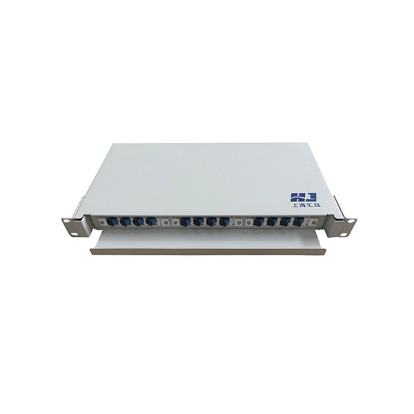
Fiber optic terminal boxes provide functions such as input, branching and splicing of optical fiber cables. Through the connectors and splicing boxes in the terminal box, optical fibers can be quickly connected and repaired. Serving as a critical connection point, FTB facilitates the termination, splicing, or connection of fibers from various cables to other network devices such as switches, routers, or Optical Network Terminals (ONTs). It aids in splicing, splitting, storing, and managing fibers within the appropriate. The optical fiber terminal box is the terminal joint of an optical cable, one end of which is an optical cable, and the other end is a pigtail, which is equivalent to a device that splits an optical cable into a single optical fiber. A fiber pigtail is a specific hardware connection used for cable termination. It is a small enclosure that can house and protect the fiber optic cables, splices, and connectors. The optical fiber termination box and optical fiber splice box serve distinct purposes and are not interchangeable.
[PDF]
1x9 transceivers are the earliest and oldest-style optical modules. Initially created in the 1990s, they aimed at 100M/1G Ethernet, Fibre Channel, ATM, FDDI, SDH/SONET, and video applications. Then, they were gradually replaced by more advanced and intelligent GBICs, SFPs . Next, we will introduce the three main features of the optical module: The package form is the most important feature of the optical module. The earliest package form was 1*9, and then GBIC, SFF, SFP, Xenpak, X2, XFP, etc. came one after another. Due to the limitations of the era, the 10G optical. An optical module is a typically hot-pluggable optical transceiver used in high-bandwidth data communications applications. The unsung heroes behind this "data voyage" are optical modules—the "optical communication translators" that precisely convert electrical and optical signals. From. Before the 1990s, there was no concept of the optical transceiver industry, and equipment manufacturers independently designed and developed optical transceivers with no uniform standards for size and mechanical interfaces, resulting in poor compatibility and connectivity issues for telecom.
[PDF]

This paper is focused on the performance analysis of protection mechanisms utilized in common wavelength division multiplexing-based passive optical networks. Wavelength division multiplexers are fundamental to the functioning and performance of integrated photonic circuits, with applications ranging from optical interconnects to sensing and quantum technologies. Current solutions are limited by trade-offs between channel spacing, crosstalk, insertion. Wavelength division multiplexing (WDM) is a technology for increasing the transmission capacity of optical fiber communications by sending multiple data channels simultaneously through a single fiber, each on a different wavelength of light. The main aim of the proposed research is providing an option of comparing different traffic protection scenarios for advanced optical. Herein, an attention-grabbing and up-to-date review related to major multiplexing techniques is presented which includes wavelength division multiplexing (WDM), polarization division multiplexing (PDM), space division multiplexing (SDM), mode division multiplexing (MDM) and orbital angular momentum. The journey of optical multiplexing began in the 1970s with the introduction of Wavelength Division Multiplexing (WDM), which revolutionized the capacity of optical communication systems. The primary objective of optical multiplexing has been to maximize the utilization of available bandwidth in.
[PDF]
Find low everyday prices and buy online for delivery or in-store pick-up. Find low everyday prices and buy online for delivery or in-store pick-up. Shop products from small business brands sold in Amazon's store. Discover more about the small businesses partnering with Amazon and Amazon's commitment to empowering them. Learn more Made with chemicals safer for human health and the environment. Manufactured on farms or in facilities that protect. 20pcs Transmission Type Photoelectric Switch Optical Interrupter Sensor Opto. OPB825 Opto optical switch, photointerrupter. SA-6C Digital Toslink Optical 4x1 Switch with 3ft Optical Cable and IR Remote Contr. Get the best deals on optical switch when you shop the largest online selection at. Shop for Optical switcher at Best Buy. Networx® Gigabit Ethernet Fiber Media Converter - UTP to 1000Base-SX - ST Multimode, 5. Get fast shipping and top-rated customer service. Price when purchased online Cisco IE-4010-16S12P Ethernet Switch - 12 Ports - Manageable - Gigabit Ethernet - 1000Base-X, 10/100/1000Base-T - 3 Layer Supported - Modular - 16 SFP Slots - Optical Fiber, Twisted Pair - 1U - Rac. Live better. The FOSW-1x1 or 1x2 optical switch is based on opto-mechanical technology with proven reliability.
[PDF]
6Wresearch actively monitors the Barbados Optical Fiber Cables Market and publishes its comprehensive annual report, highlighting emerging trends, growth drivers, revenue analysis, and forecast outlook. Our insights help businesses to make data-backed strategic decisions with. Equipment may be required for some packages & features. Pricing may vary depending on service area. Lifeline or Basic service needed for additional TV packages. Additional equipment may be required. Whether you are a professional or a DIY'er: at Kooyman we'll get you started! From home electronics to energy-efficient air conditioners, we have everything you need to power up your space. Our expertise extends to impeccable electrical finishing and electrical installations, ensuring your home. Barbados' leading IT, Computer & Consumer Electronics Superstore Retailer. From custom-surfaced prescriptions to ready-stock finished lenses, we provide comprehensive solutions for optical professionals. Available in single vision, bifocal, and progressive designs. Ready-to-edge stock lenses for. Moved Permanently. Redirecting to https://cartersonline. bb/electrical/cable-and-accessories/cables. Immerse yourself in a world of unparalleled variety as we offer an extensive array of extraordinary electrical products for your discerning needs. From top-notch outlets.
[PDF]

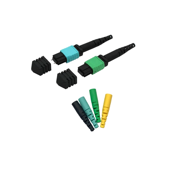
1: Use kevlar scissors to cut the cable at the middle. We'll splice the two pieces back together in an exercise and put new connectors on the bare ends in another exercise. Marcel Buijs, EMEA Business Development, Technical Sales, Fiber Optic Center, Inc. with over twenty-five years in the photonics industry, brings the latest information on making the ultimate fiber optic product and improving process yield. Without question, good stripping techniques in your fiber. Use the Wire Stripper/Splitter to strip a variety of fiber optic and coaxial cables up to 14 mm in diameter. This stripping tool provides a comfortable and secure grip to help make the fiber stripping process easy and efficient. In our continuing discussion of installing FO cables, let's use a step-by-step approach in detailing how to strip and clean indoor and. An Optical Fiber Stripper is arguably the most fundamental hand tool for any technician working with fiber optic networks. In an industry where precision is not just a goal but a requirement, the quality of your stripping tool directly impacts signal integrity, network reliability, and overall. Optical fibers are typically protected with fiber coatings made from polymers such as acrylate, silicone or polyimide. For splicing, connectorization or other processing, these coatings must be removed. Fiber strippers are precision tools that reliably and cleanly remove a defined length of coating. Safety Rules - Read before beginning any exercises.
[PDF]