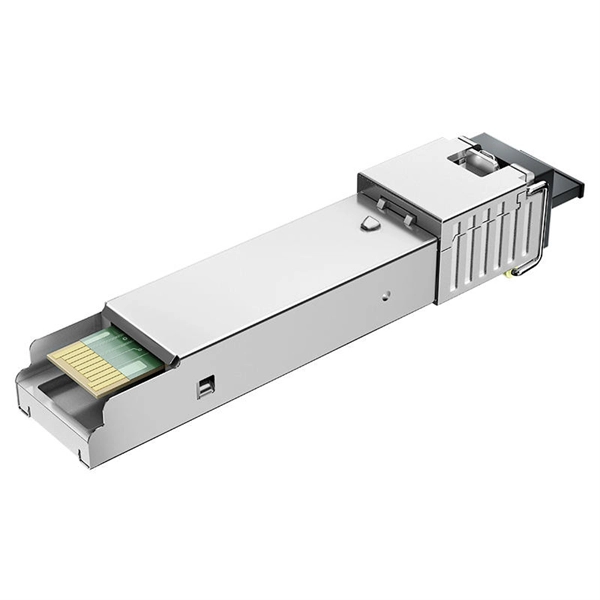
Yes, it is possible and often recommended to run fiber optic cables through conduit. This practice provides several benefits, including protection from physical damage, environmental hazards, and unauthorized access. Whether you're setting up a network in your home or installing fiber optic cables for a large-scale project, one crucial factor to consider is the conduit. The conduit protects the fragile fiber optic cables from environmental factors and physical damage, ensuring their longevity and optimal. Whether you're working on a data center buildout, a city-wide fiber network, or upgrading rural network links, selecting the right cable conduit ensures overall cost-efficiency along with long-term reliability for your project. Outdoor cable may be direct buried, pulled or blown into conduit or innerduct, or installed aerially between poles. Indoor cables can be installed in raceways, cable trays above ceilings or under. Installing the fiber inside protective tubing, known as conduit, is standard practice for any durable installation, ensuring the longevity and reliability of the connection. Placing fiber optic cable inside a conduit is a necessary investment because the protective tubing addresses three major. This article examines common methods for installing indoor optical fiber and outlines the requirements for the job. OPGW, all-dielectric self-supporting cable, and OSFP 400G transceivers are part of modern SDGI, so we'll also discuss it.
[PDF]
144 fiber breakout cables are commonly used in the consolidation of 72 duplex fiber cables, and reduce unnecessary bulk and cost associated with numerous individual fiber cables. 144 fiber breakout cables include LC, SC, or ST connectors, and are available in Single-mode (OS2) or. Corning recommends storing cable in a proper temperature environment prior to installation to allow the cable temperature to meet installation temperature range specifications for best installation results. Tensile Strength, Long-Term Max. Tensile Strength, Short-Term Corning ALTOS®. Introducing our premium 144 Core Fiber Optic Cable Enclosure, designed for robust and reliable performance in demanding telecommunications environments. This high-capacity enclosure is engineered to protect and manage up to 144 fiber optic cores, ensuring seamless connectivity for your network. Fiber Cable, Singlemode, 144 ct., Single Jacket, Single Armor, Single Jacket, Loose Tube, Reduced Water Peak, Dry/Dry, Price Per Ft., Our reels have a manufacturing variance up to 5%, you will be billed for the quantity that ships. LightScope ZWP® Fiber Cable, Singlemode, 48 ct., Single Jacket. Corning Cable Systems ALTOS® Cable with FastAccess™ Technology is an all-dielectric gel-free cable designed for outdoor and limited indoor use for campus backbones in lashed aerial and duct installations.
[PDF]
Fiber Breakage: Single-mode fiber optic cables can be prone to fiber breakage, which can result in signal loss. Fiber breakage can occur from physical damage, such as bending or crushing the cable. This can cause signal attenuation and may even result in signal loss. To avoid bend loss, it is important to follow the minimum bend radius specified by the cable manufacturer. NEATEL's The Single-Mode (SM) Breakout Indoor Fiber Cable is designed for high-performance, secure fiber optic connectivity in indoor environments. Unlike tight-buffered fiber cables, this breakout-style cable features multiple individually reinforced sub-cables (typically 2. Tension and stress: Fiber optic cables can be damaged if they are subjected to too much tension or stress, as this can cause the fibers to break. Fiber design and transmission technology have collaboratively evolved to increase bandwidth. Dig-ups dominate! Cablers have very little influence on the majority of causes of cable field failures. While a small percentage, we can examine the “intrinsic” cable failures and what is done to prevent. Recommendation ITU-T L. 103 describes characteristics, construction and test methods for optical fibre cables for indoor applications. In order for an optical fibre to perform appropriately, characteristics that a cable should have been described. Also, the method of determining whether the cable.
[PDF]
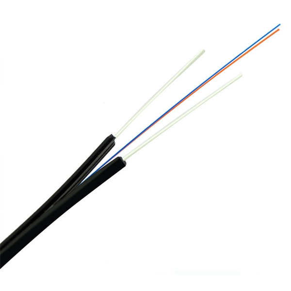
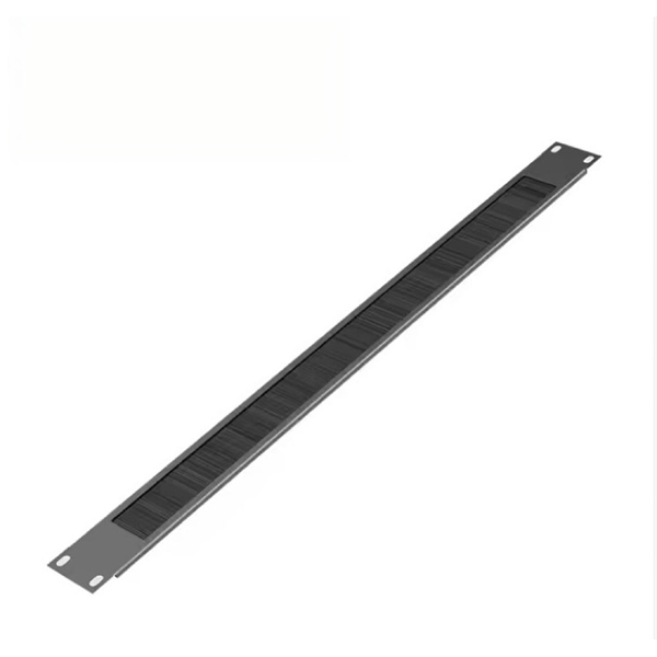
This is where the advantages of fiber optics, specifically indoor fiber optic cable, become apparent. Offering superior bandwidth, lower latency, and enhanced security, it has become the gold standard for future-proofing indoor network infrastructure. Indoor fiber cable is the backbone of modern communication networks within buildings, providing the high-speed data transmission necessary for everything from business operations to home entertainment. As our reliance on fast, reliable internet connectivity grows, so does the importance of. These indoor cabling fibers (drop cables) are those that connect ducts inside the buildings to individual rooms/floors. They are essential for high-rise buildings, data centers, and urban environments containing dense populations where fast, fire-safe, and flexible fiber installations are. Wall-mounted fiber optic wiring boxes are devices used for organizing and managing fiber optic cables in a building or data center. They can be used for various applications such as data transmission, telecommunication, and multimedia. Each type is designed with specific features to ensure optimal performance under varying conditions. This guide explores common indoor cable varieties and their distinct attributes when wiring rooms or structures for high-speed fiber optic links. While outdoor cables.
[PDF]

The machine is a hand-held free-to-height cable quick-attachment tool with internal components such as controllers that automatically complete all steps of cable tying. It can be widely used in the high-altitude operation in the field of communication engineering and is. Power Source: Rechargeable lithium battery Bundling range: 0-60mm Binding : can binding 1600 times for one time fully charger. Voltage: 12V Battery: 7800 mAh/group, Fully charged, one battery can work more than 1600 times, about 3 kilometers or more Battery installation mode: external and embedded. Delivery time is estimated using our proprietary method which is based on the buyer's proximity to the item location, the shipping service selected, the seller's shipping history, and other factors. Delivery times may vary, especially during peak periods. Buyer pays for return. Buy Newly Designed Second Generation High Altitude Optical Fiber Cable Bundling Machine for Efficient Network Installation at Aliexpress for. Find more 1420, 153713 and 1537 products. Enjoy ✓Free Shipping Worldwide! ✓Limited Time Sale ✓Easy Return. Maximum order quantity: 1 piece Customized logo (+ from /Min.
[PDF]

Bury cables from 12-36 inches (or 30-90 cm) deep. Where plant life, sidewalks, and other utilities already disrupt earth, it's safer to bury at as little as 24 inches or 60 cm, using protective conduits to limit the likelihood of damaged cables by inexperienced maintenance or. Bury cables from 12-36 inches (or 30-90 cm) deep. However, simply hitting this depth isn't enough to guarantee your network survives. Factors like the. Requirements vary based on location, cable type, and local regulations, with depths typically ranging from 18 to 48 inches. Residential areas require depths between 24 and 36 inches for most installations. This protects cables from landscaping activities and minor excavation work. This. The question of how deep to bury fiber optic cable has no single answer, as the required depth changes significantly based on location, environment, and specific application. Industry standards and regulations, such as those often referenced in the National Electrical Code (NEC), establish a. Fiber optic cables are typically buried between 12 and 36 inches (30–90 cm), depending on installation environment, soil conditions, and load requirements. In high-load areas such as roads or backbone routes, burial depth can reach 48 inches (120 cm) or more. This guide provides a comprehensive overview of industry.
[PDF]
A fiber-optic cable, also known as an optical-fiber cable, is an assembly similar to an but containing one or more that are used to carry light. The optical fiber elements are typically individually coated with plastic layers and contained in a protective tube suitable for the environment where the cable is used. Different types of cable are used for in different applications, for exa.
[PDF]
There are hybrid optical and electrical cables that are used in wireless outdoor Fiber To The Antenna (FTTA) applications. In these cables, the optical fibers carry information, and the electrical conductors are used to transmit power. These cables can be placed in several environments to serve antennas mounted on poles, towers, and other structures. According to Telcordia GR-3173, Gener. OverviewA fiber-optic cable, also known as an optical-fiber cable, is an assembly similar to an but containing one or more that are used to carry light. The optical fiber elements are typically individually. Optical fiber consists of a and a layer, selected for due to the difference in the between the two. In practical fibers, the cladding is usually coated wit. In September 2012, NTT Japan demonstrated a single fiber cable that was able to transfer 1 per second (10 bits/s) over a distance of 50 kilometers. Although larger cables are available, the highest stra.
[PDF]
The cost to install fiber optic cable ranges from $1. 50 to $42 per foot, with installation costs accounting for 60-80% of total project expenses. According to the Fiber Broadband Association's 2025 report, median costs are $8 per foot for aerial builds and $18 per foot for. Fiber optic cable installation costs between $1,500 and $7,000 for your home, with prices varying by cable length and installation method. The installation type you choose and the layout of your property determine the total labor and materials needed for your project. You should account for permit. The initial cost of installing fiber optic cables can vary depending on the chosen installation method and specific project requirements. Total Project Costs: For commercial installations, expect costs ranging from $5,000 to $20,000 per mile for underground projects and from $40,000 to $60,000 per. Homeowners and businesses typically pay for fiber optic cable installation based on distance, conduit needs, and labor. The main cost drivers include material type, run length, trenching or aerial work, and any required permits or inspections. This comprehensive guide breaks down the factors influencing pricing, average expenses, and tips to get the best value in 2025. Clear insights help make informed decisions without unexpected surprises. Let's start by getting a better idea about the material cost. Understanding the fiber cable cost per foot is crucial before.
[PDF]

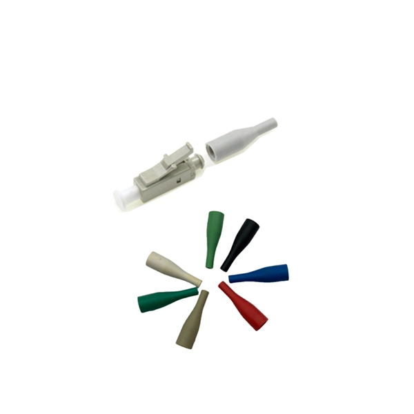
Without proper crimping, even minor movements can cause the cable's fibers to shift, resulting in a weak or broken connection. it also facilitates a smooth and efficient signal. When manufacturing fiber optic cable assemblies, a relatively simple step can have dire consequences if not done accurately. This is true for crimping. In fact, once all. To attach the connector to the fiber, the installer can use glue or crimping. An epoxy or other adhesive can be used to glue the fiber into the connector's ferrule, and the end of the fiber then polished. The epoxy needs curing, which can take overnight, or be speeded up using a curing oven. An. We terminate fiber optic cable two ways - with connectors that can mate two fibers to create a temporary joint and/or connect the fiber to a piece of network gear or with splices which create a permanent joint between the two fibers. A poor crimp will lead to mechanical distress resulting in optical performance d perator's training and manufacturing engineering support. The purpose of this document is to provide guidance on SENKO's recommended nted for electrical. At the heart of any robust fiber optic network lies a crucial process: Preparing a fiber cable for termination of a connector or splice. Two types of splices are used in fiber optic cabling one is Mechanical the other is Fusion. Whether you're installing a new network, expanding an existing one, or.
[PDF]

TendersOnTime, the best online tenders portal, provides latest South Africa Optical Fibre tenders, RFP, Bids and eprocurement notices from various states and counties in South Africa. TendersOnTime, the most comprehensive database for Government Tenders and International Tenders; collects. See below for a list of Fibre Optic Supplies, Installation and Maintenance Tenders. These tenders can consist of Request for Information (RFI), Request for Quotation (RFQ), Request for Proposal (RFP), Expression of Interest (EOI) or Request for Tender (RFT) listings. com offers an unmatched database of Optical Fibre Cables tenders from South Africa, more than any other platform. Daily, new procurement. Pricing (USD) Filter the results in the table by unit price based on your quantity. Armored Fibre Optic Cables are available at Mouser Electronics. Mouser offers inventory, pricing, & datasheets for Armored Fibre Optic Cables. 350 Optic Fibre Tender are matched from various African Government and Local Tendering Authority & Private companies. install and test the underground optic fibre from harvard substation to eskom centre control room in. INVITATION TO TENDER (ITT) FOR THE DESIGN, MANUFACTURE, SUPPLY AND DELIVERY OF ESTIMATED QUANTITIES OF OPTICAL GROUND WIRE (OPGW) CABLES ON AN AS AND WHEN REQUIRED BASIS FOR A PERIOD OF FIVE (5) YEARS.
[PDF]
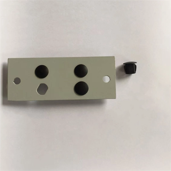
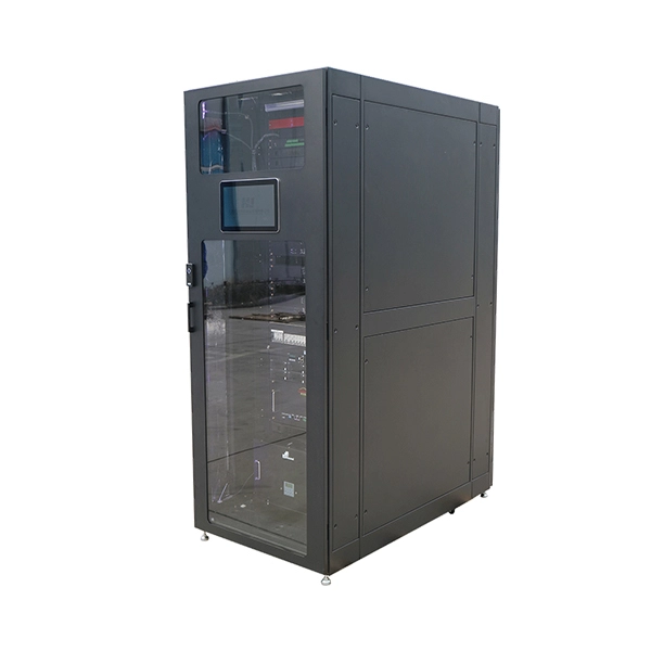
Incoming Distribution Cable: The fiber distribution box receives an incoming distribution cable, which typically carries a bundle of optical fibers. These optical fibers originate from a central source, such as a data center, central office, or distribution point. Fiber Distribution Boxes (FDBs) are critical components in modern telecommunications infrastructure, particularly in fiber optic networks. Minimize the interference of the optical cable access signal to the external environment. The. In the complex architecture of fiber optic networks, the Optical Distribution Frame (ODF) serves as the linchpin for organizing, protecting, and distributing optical signals. Whether in data centers, telecom central offices, or enterprise network rooms, ODFs enable efficient fiber management. An optical cable consists of three primary parts: the core, the cladding, and the protective sheath. Surrounding the core is the cladding, which has a lower refractive index than the core. This complete guide explores everything you need to know about ODFs — from their structure, types, and key components, to installation best practices and modern design trends. Whether you're building a central office, data center, or FTTx distribution network, understanding the right ODF.
[PDF]

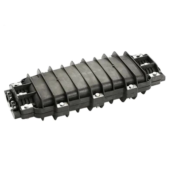
In this step-by-step tutorial, we show you exactly how to place a fusion splice safely and securely inside a Coyote fiber optic splice enclosure. Fiber cable splicing is a critical step in building reliable fiber optic networks. Whether in data centers, telecom rooms, or outdoor FTTx deployments, proper splicing inside a fiber enclosure ensures low signal loss, long-term stability, and easy maintenance. This guide explains what fiber cable. Think of a fiber optic cable splice as the seamless stitching that keeps data flowing through the delicate threads of a network—like a master tailor joining fabric with precision. Whether repairing a broken cable or extending a fiber run, fiber optic splicing ensures light signals travel. In addition to the outer skin of the optical cable (if any, please remove the shielding and armoring) and then remove each wrapping layer until the loose tube is exposed. Make sure you read and understand this instruction as well as instructions provided with related assemblies before. In this guide, we cover the basics of fiber optic splicing, how to perform splicing using two different methods, and finally some best practices to perform good fiber splicing. What is Fiber Optic Splicing and Why is it Needed? – #1. Use and Maintain Your.
[PDF]