
Telescopic mast system with advanced vibration-dampening technology to minimize jitter and ensure stable communication and data transmission, even in the most demanding terrain and vehicle movements. Fireco designs and manufactures the most comprehensive line of standard and custom telescopic masts using high quality materials with industry leading engineering and quality testing practices to provide our customers with the world's best mobile masts. Will-Burt's telescopic masts and tower systems provide intelligent. Telescopic mast systems play a critical role in modern field operations—enabling elevation of cameras, antennas, lights, sensors, and communication gear in demanding environments. Whether for surveillance, broadcasting, defense, or emergency response, choosing the right mast system ensures reliable. Floatograph, along with its utility industry partner, Eversource Energy, developed the Rapid Pole® – Temporary Power Pole system to reduce customer downtime, allowing crews to re-energize a circuit in as little as 20 minutes. Floatograph's masts come in height options from 10 to 100 feet, and are. Advanced telescopic mast solutions designed for versatility in the field, providing crucial support for on-the-move (OTM) missions. Erecting the Telescoping Mast is made by simply connecting guys and brackets to the attached unique heavy duty rolled edge guy rings and clamps, extend the sections, insert the locking cotter pins, rotating the tubes to.
[PDF]
An optical fiber is a cylindrical ( waveguide) that transmits light along its axis through the process of total internal reflection. The fiber consists of a core surrounded by a layer, both of which are made of materials. To confine the optical signal in the core, the of the core must be greater than that of the cladding. The boundary between the core and cladding m.
[PDF]
The zero-buoyancy rov cable was born as a power connection and control of underwater robot equipment, as well as signal transmission and feedback link cable applications. The zero-buoyancy cable has been tested by the market and practice due to its excellent. The global underwater zero buoyancy cable market is experiencing robust growth, driven by the expanding offshore energy sector, increasing demand for subsea infrastructure development, and advancements in underwater communication technologies. Linden Photonics is renowned for its innovative fiber-optic solutions, specifically designed for Remote Operated Vehicles (ROVs). These ROV tethers are crucial in underwater applications, offering high performance, durability, and reliability in challenging environments. For use with ROV's (Remote.. Customizable neutral buoyancy fiber optic power cable for ROVs and underwater drones. High‑performance hybrid design combining power and data in one composite cable. Engineered for seawater resistance, flexibility and subsea reliability. Suitable for inspection systems, subsea cameras and. At Invocean, we understand the increasing demands and the critical nature of Remotely Operated Vehicles (ROVs) in various industries such as underwater construction, surveillance, salvage, and scientific research. To support these high-performance tasks, ROVs and Micro-ROV's require reliable.
[PDF]

Managing optical attenuation helps keep your signal safe. Clean your optical connectors so you do not lose. Optical Signal Attenuation is the single greatest factor limiting the distance and performance of your network. Understanding it is crucial for anyone involved in data centers, telecommunications, or enterprise networking. This guide will demystify signal loss, explore its causes, and show you how. In high-speed environments, where the optical link budget is measured in fractions of a decibel, diagnosing and eliminating unexpected loss is the network engineer's most critical task. This field guide provides a systematic, step-by-step approach to troubleshooting and resolving the most common. Signal loss in Fiber Optic networks can make data slow. It can also break your connection. You should fix it fast to get speed and stability back. > You can solve this with simple steps. Signal Degradation (Loss of Light) When the signal quality degrades, it could be a sign of attenuation or excessive loss in the system. The signal might become weaker, resulting in slower speeds or dropped connections. -. Fiber optic networks are celebrated for their speed and reliability, but even the best systems can encounter problems. When issues like signal loss, slow speeds, or intermittent connectivity arise, systematic troubleshooting is key. Things like impurities in the fiber core and reflections at the core-cladding edge cause this drop.
[PDF]
Optical modules have a series of components inside, some of which have received attention from standards development organizations. In many cases, the baud rate of the optical interface does not equal the baud rate of the electrical interface. In these cases, a gearbox is used within the module to convert between the two rates. For example if the module supports 4 x 25 Gb/s electrical inputs and 2 wavelengths of 50 Gb/s optical inte.
[PDF]
A fiber-optic cable, also known as an optical-fiber cable, is an assembly similar to an but containing one or more that are used to carry light. The optical fiber elements are typically individually coated with plastic layers and contained in a protective tube suitable for the environment where the cable is used. Different types of cable are used for in different applications, for exa.
[PDF]
Optical modules are essential components in modern communication networks, enabling high-speed data transmission over fiber optic cables. As the demand for faster and more reliable internet and data services grows, understanding these devices becomes increasingly important. Optical modules typically have an electrical interface on the side that connects to the inside of the system and an optical interface on the side that connects to the outside. That is, metal medium communication represented by coaxial cables and network cables is gradually being replaced by optical fiber media. Composition of Optical Modules The optical module, known as Optical Transceiver in. The optical module serves as a crucial component in optical fiber communication systems, operating at the physical layer, which is the lowest layer in the OSI model. Its primary function is to achieve optoelectronic conversion by converting electrical signals into optical signals and vice versa.
[PDF]

These core components of optical fiber communication system — transmitter, optical fiber, receiver, plus supporting elements like amplifiers and multiplexers — enable lightning-fast, interference-free communication over vast distances. Fiber optic communication refers to a method of transmitting data that utilizes light instead of electrical signals to send information through optical fibers. It works on the principle of total internal reflection, allowing light to move through the fiber with very little loss. The process kicks. In order to comprehend how fiber optic applications work, it is important to understand the components of a fiber optic link. Simplistically, there are four main components in a fiber optic link (Figure 1). These systems rely on three vital components working together – the communication channel, the optical transmitter, and the optical receiver. Optical fiber communication system 1. Encoder Encoder converts the analog information like voice, figures, objects etc into the binary data. Optical fibers are thin, flexible strands of glass or plastic that serve as the medium for transmitting light signals. Some exceptional characteristic features of this type of communication system like large bandwidth, smaller diameter, lightweight, long-distance signal.
[PDF]

This procurement guide curates leading SFP module manufacturers and suppliers in Europe, summarizes their differentiators, and offers practical buying tips. ESTEL designs and manufactures high‑performance optical transceivers in Europe and in the US, with local technical support and a secure supply chain. Our optical modules power demanding telecom and datacom networks across data centers, metro and long‑haul links. Browse optical transceivers Talk to. Transceiver stands for Transmitter/Receiver Module. These (opto-)electronic devices allow data transmission over copper and fiber cables. A wide range of form factors are available allowing data rates from 100Mbps up to 800Gbps. Skylane Optics offers the full range of transceivers with an unique. We are committed to providing high-performing optics and transceivers through professional and reliable capabilities. Equipped with the most extensive and stringent testing and solution designing processes. Delivered fast, tested, and 100% compatible with your hardware. Swedish Telecom Opto is built for scale — not single-click sales. We work with mid to large organizations, supporting. There are 317 Optical Products Manufacturers in Southern Europe as of August 15, 2024; which is an 1. 26% increase from 2023. With over two decades of experience in the industry, we specialize in designing and producing high-quality optical components for a wide range of applications. Our team of skilled engineers and technicians are.
[PDF]
In telecommunications, a base station is a fixed transceiver that is the main communication point for one or more wireless mobile client devices. It further connects the device to other. A communication base station is composed of a computer room, base station, antenna, feeder line (transmission line between transmitter and antenna), and supporting equipment. The antenna is at the top of the signal tower, and below the tower is a computer room. Along with increased capacity demands driven by the explosion of cloud and connected device growth, engineers need interconnects that enhance the design. A base transceiver station (BTS) or a baseband unit (BBU) is a piece of equipment that facilitates wireless communication between user equipment (UE) and a network. UEs are devices like mobile phones (handsets), WLL phones, computers with wireless Internet connectivity, or antennas mounted on. Fiber Optic Cables: High-speed fiber optic cables connect the BBU to the RRUs (RE part). Signal Transmission: The optical signals carry data, control, management, and synchronization information. Topology: The BBU and multiple radio heads can be connected in cascade or star configurations. The rise. The design investigates the possibilities of Free-Space Optical (FSO) communication systems and MilliMeter-Wave (MMW) technologies operating at 60. Although these technologies are highly effective and have a high throughput, they are nevertheless vulnerable to weather phenomena like rain.
[PDF]
These easy-to-install 20" cable channels can be painted, cut and even turn a 90º angle. Simply attach the uniquely designed wall clips to the wall, secure cables and wires to the fasteners and snap the tunnels onto the clips. Kit includes three long cable . Corning has a wide variety of hardware solutions to choose from to fit your cabling needs. Choose from racks, panels, modules, splice trays, ethernet fiber switches and other structured cabling components. Corning has a variety of hardware solutions including ethernet fiber switches, panels, racks. Often over looked, utilizing tunnel systems to deploy fiber optics, can provide last-mile and intra-city broadband pathways by providing immediate, cost-e ective, and durable deployment routes without disrupting the municipality or mother nature. This fact presents Transit Operators with a unique. Cable Tunnel Kit: The Sanus ELM301 is a cable tunnel kit that conceals and routes even the most complex cable arrangements. This concept significantly optimises the lighting installation. Precision Group's Optical Network Terminals are engineered to safeguard both the ONT and fiber, serving as a secure, all-in-one transition point. Based on customer feedback, our latest optical network terminal designs now include Keystone Ports for router and phone connections, enhancing.
[PDF]

Do you need a reliable, durable, and easy-to-install solution for your fiber optic cables? You're in the right place! Our product, consisting of a stainless steel wire and a reinforced nylon body, is specially designed for drop cables with diameters up to 3-8mm. ADSS Anchor Tension Clamps are hardware fittings used to securely terminate and anchor ADSS fiber optic cables on poles or towers without damaging the cable. They are lightweight and economical, allowing for easy installation, and suitable where environmental performance is low. At the same time, the plastic is thick enough not to break within the studied period, making it ideal for. In 2015, Jera line started to produce clamps and brackets for FTTX fiber optic cable deployment. With a combination of stainless steel wire and reinforced nylon body, Fibeye tension clamps offer excellent durability and performance. Do you need a reliable, durable, and. MefiberOptic. com provide a complete solution of products for fiber optic cable deployment for FTTx network constructions. We supply various clamps and brackets for ADSS or drop cable install solutions. Jera is. Each accessory serves a specific purpose: fiber tension clamps provide the right tension without damaging cables, drop wire clamps secure cables in outdoor environments, and anchor hooks and brackets support and stabilize cables on poles, walls, or buildings. Together, these accessories ensure that.
[PDF]

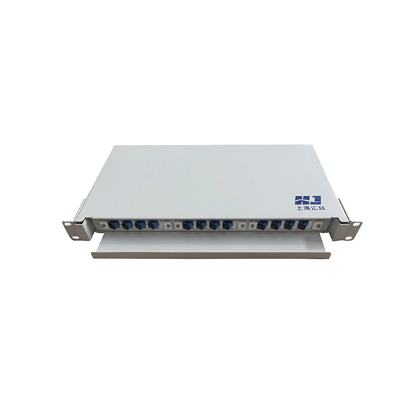
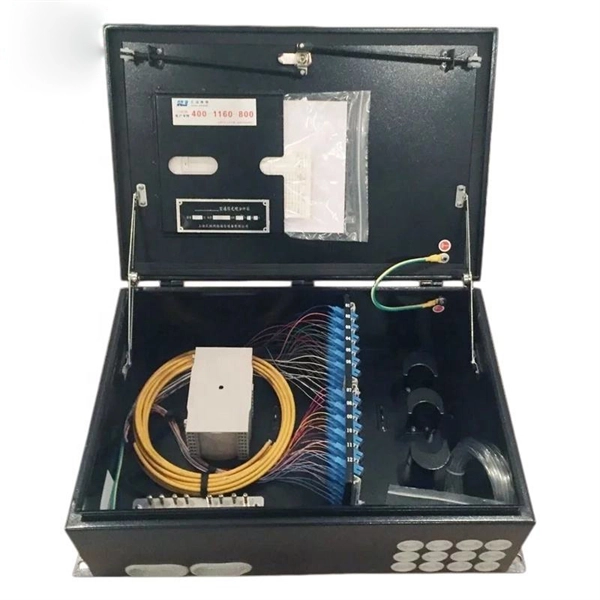
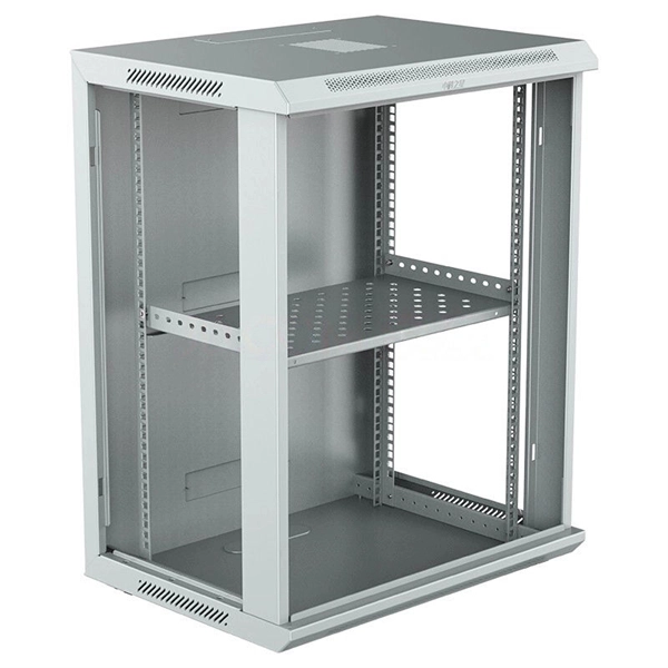
First, connect each pre-terminated fiber optic cable to the adapter panel separately, making sure the ports correspond one-to-one; then fix the fiber optic adapter panel to the front panel of the distribution box with the bend radius control clip. In general, installing the optical fiber distribution box can be divided into three steps: installing the optical fiber distribution box on the rack, introducing the optical cable into the optical fiber distribution box, and planning the optical fiber path in the optical fiber distribution box. The. Bottom installation: Select a proper installation position in the equipment room and drill four holes in the floor according to the dimensions shown in the manual. Fix the rack to the ground with expansion bolts. Top installation: Dimensions of four connection holes on the top according to the. The Optical Distribution Box (ODB) is high-density 2-in-2-out fiber box solution. Designing with a compact size of 340x220x100mm, the cabinet accommodates 1x2,1x4,1x8 and 1x16 etc. The 4 ports are sized for main cable from 9 to 16mm in diameter, along with 16 3mm cables. Accessory Kits:. Install the optical fiber distribution box on the rack. Ensure that the box is installed firmly and horizontally, and the deviation of perpendicularity is not greater than 3mm.
[PDF]


