In this paper, we present this new method of building OMS-OOCCN or its model. System design Our method applies three key information processing techniques such as geographic information system (GIS), simulation and expert system (ES) ones. We developed a specialized Geographic Information System for an internet service provider operating a fiber-optic network across multiple neighboring locations. Really, they are also the most important techniques for. Location Data (C. Summary of descriptive data (C. Manage Fiber Optics Network (maintenance &operation) (C. Final. A leading telecom infrastructure provider responsible for planning, deploying, and maintaining optical fibre cable (OFC) networks to expand digital connectivity across urban and rural regions. The client needed a reliable and accurate system to document, monitor, and manage thousands of kilometers.
[PDF]

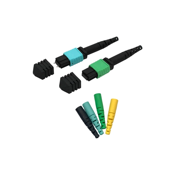
Optical attenuators use several principles in order to accomplish the desired power reduction. The types of attenuators generally used are fixed, stepwise variable, and. An optical attenuator is a passive device that is used to reduce the power level of an optical signal. The attenuator circuit will allow a known source of power to be reduced by a predetermined factor, which is usually expressed as decibels. Key requirements include minimal effect on the beam profile, low wavelength and polarization dependence, and sufficient power handling capability. The basic types of optical attenuators are fixed, step-wise variable, and continuously variable. Since too much light may saturate the fiber optic receiver, optical attenuators are often deployed in the system to reduce the light power and achieve the best fiber. An attenuator is a device designed to reduce the intensity of electrical and electromagnetic oscillations smoothly, stepwise, or at a fixed rate. It primarily ensures the power or amplitude of a signal is lowered without significantly distorting its waveform. Attenuators are extensively used across.
[PDF]

DFM in optical design refers to the process of designing optical components and systems that are manufacturable, testable, and inspectable. The importance of DFM lies in its ability to reduce production costs, improve product quality, and accelerate time-to-market. The SPIE Digital Library's coverage of design for manufacturability (DFM) predominantly centers on semiconductor and optical system manufacturing. The content heavily emphasizes photolithography-related DFM, detailing techniques for optimizing mask designs, optical proximity correction, and. Design for manufacturability (DFM) is a critical first step in the development of any optical component. In the context of optics, DFM involves optimizing the design of optical components and systems to minimize production costs, reduce. Optical assembly manufacturing combines precision components such as lenses, prisms, mirrors, and other components that must perform in demanding environments. Taking complex optical systems from simulation into production involves meeting a range of mechanical, functional, and other requirements. Today, we are expanding my very first blogpost from 2020 and discussing the concept of Design for Manufacturability (DFM). In this article, we explore why DFM matters and how key design aspects influence the success of plastic optics. Understand the Limitations of Injection Molding.
[PDF]
Get price quotes for Fiber Bragg Grating. Contact suppliers directly with one click. Use this fiber Bragg gratings buying guide to compare major types, define selection criteria, and find suppliers: Professional purchasing of high-value photonics products is a substantial responsibility, where a structured decision-making process is essential. RP Photonics offers a lot of help: Get. Comparing fiber bragg grating sensor prices. How does 6W market outlook report help businesses in making decisions? 6W monitors the market across 60+ countries Globally, publishing an annual market outlook report that analyses trends, key drivers, Size, Volume, Revenue, opportunities, and market segments. All our Fiber Bragg Grating Arrays and Cable models are designed to make handling and deployment fast, easy and intuitive. Technica. Transmission spectrum for a sample FBG with center wavelength of 1546. 83nm and 90% reflectivity: Please note: the FBG is made on bare single mode fiber and has no steel tube or any other types of package. © 2024 CB Cabling Technologies Ltd.
[PDF]

On average, you can rent a Fusion Splicer for $275/day, $773/week, $1424/month. The price of these splicers can be higher because of their mechanical complexity and ability to handle various fiber types, including large-core fibers. Hybrid splicers bring in various features that are present in both automatic splicers and manual splicers. They can be aligned by the core. Fiber optic fusion splicers are critical tools for deploying and maintaining fiber networks, with significant variations in performance, features, and pricing. This guide breaks down the key cost-influencing factors across five dimensions—splicer types, technology, performance, accessories, and. A fiber optic splicing machine is a specialized machine used to fuse two optical fibers together to form one long one. The machine, also known as a fiber optic fusion splicer, uses electricity to melt the two optic cables into one. The fiber fusion splicer conducts the fusion with high accuracy to. Check each product page for other buying options. Get reliable equipment with fast splicing times and comprehensive accessories included. It features a mini handheld design, integrated buttons and touch screen, simple operation, low.
[PDF]
Fiber optic cables are, like their name suggests, a cable that uses light, rather than electricity to transmit information. They're made from silica glass fibers about the same width as a human hair, which all.
[PDF]
Remove and reinstall the optical module. If the fault persists, replace the optical module with a normal one of the same type to check whether the optical module is faulty. The optical module is faulty or not securely installed. The device management or driver software has a bug. If the optical module is installed on a GE port, run the display interfaceGigabitEthernet x/x/x command to view port information when the optical module is inserted, including the rate and wavelength. Have you ever dealt with sudden network drops from faulty optical modules? Issues like this cannot only break communications, but they can really jeopardize business continuity. Understanding how to troubleshoot and prevent a failing optical module is vital for good network stability. This article. Huawei switches using non-certified optical module may not be able to read the information, can not guarantee the accuracy of the information read, recommend the use of Huawei certified optical switch module. Page 5 Changes in Issue 01 (2017-09-10) This issue is the first official release. The software version of this issue is V800R010C00. Issue () Huawei Proprietary and Confidential Copyright © Huawei Technologies Co. Page 8 40º C if a 40º C if a at 40º C if a single fan single fan single fan. The device cannot display any optical module information but services are running normally.
[PDF]

The receiver of an optical module has an overload point. Therefore, an optical attenuator is required to reduce the optical power. By introducing a precise and constant amount of optical loss, it ensures that the incoming signal remains within the optimal operating range of the receiver. A. Average optical power refers to the optical power outputted by the optical module's transmitter under normal working conditions, which can be understood as the intensity of light. The transmitted optical power is related to the proportion of "1"s in the transmitted data signal; the more "1"s, the. The receiver of an optical module has an overload point. If the optical power received by the receiver is excessively high, the optical module will be burnt. In addition, during signal transmission in a WDM system, the. 📦 For purchasing, use the RP Photonics Buyer's Guide for optical attenuators. It provides an expert-curated supplier directory, buyer-focused technical background information, and structured selection criteria to support professional procurement decisions. Optical attenuators are devices that. An optical attenuator, or fiber optic attenuator, is a device used to reduce the power level of an optical signal, either in free space or in an optical fiber. Optical internetworks are data networks composed of routers and data.
[PDF]

Urban Areas: 25–40m spacing (concrete poles, 10–12m height)., steel lattice structures). Factors: Cable weight (kg/km) Ice loading (up to 50mm. The Fiber Optic Association, Inc. (FOA) was founded in 1995 to help develop the workforce to build the fiber optic networks to support a rapid expansion in communications and the Internet. The charter of the FOA was to promote professionalism in fiber optics through education, certification, and. to n utral comm. cable R. FO-CS JOINT USE CLIMBING SPACE REQUIREMENTS 51. APPENDIX A - COVER SHEET / TOC 52. RUS DRAWING #PM12 58. CHECK. d suppliers of electrical construction services. They define a minimum baseline of quality and workmanshi for installing electrical products and systems. NEIS® are intended to be referenced in contrac documents for electrical construction ation or liability to users of this publication. Choose the type of pole The basic pole height is 7m and the tip diameter is 150mm. In case of special sections, crossing obstacles or roads or railways, the pole height of 8m, 9m, etc. can be selected. Cables 300 V or less need to be a minimum two feet over the street light. Climbing Space is an unobstructed, vertical space along the side or corner of the pole. In gen-eral, it consists of an imaginary box, 30-inches square, extending at least 40 inches above the highest communications cable or.
[PDF]
Cost ranges for a residential fiber optic cable run typically span from $1,000 to $12,000, with most projects landing in the $3,000–$8,000 band. The main drivers are trench depth and length, whether the line is buried or aerial, and the in-home termination requirements. The main cost drivers are materials, installation time, and environmental factors that affect trenching, conduit, and terminations. This article provides cost. Installing an optical fiber network is a significant investment that requires careful financial planning. Whether you're upgrading an existing system or starting from scratch, understanding the costs involved can help you allocate your budget wisely. This guide will walk you through the key factors. How Much Does Fiber Optic Cable Cost per Foot? On average, commercial projects range from $5,000 to $20,000 per mile underground and $40,000 to $60,000 per mile for aerial deployment. Individual business connections often cost between $15,000 and $30,000 for 100–200 network drops. Hiring. Homeowners typically pay a broad range for running fiber optic cable from the street to a residence, with the main cost drivers being trenching or aerial installations, cable material, labor time, and permit requirements. The price also varies by fiber type (GPON vs. The price or cost to install fiber reflects material choices, labor hours, and local regulations, with per-mile and per-ft metrics common in.
[PDF]

When selecting a 48 core fiber optic cable, prioritize single-mode over multimode for long-distance, high-bandwidth applications such as telecom backbones or data center interconnects. Look for cables with loose tube construction, robust armor (if outdoor use), low attenuation (<0. 4 dB/km at 1310. • Fiber optic cables are often custom cut to match required lengths for each cable run, or you can order a reel matching your total length and cut segments yourself. It's advisable to include a safety buffer when ordering, with an additional 10% being common practice, despite careful measurement of. Fast data transmission, thinner, lighter cables and long signal range are just a few of the benefits that make fiber optic cable a solid choice for corporate data networking and telecommunications. Fiber cores are the heart of fiber optic cables, transmitting light signals that carry data. Made from either high-quality. But when it comes to selecting the right fiber optic cable for your environment, there are several key considerations and a variety of attributes to choose from, ranging from type of fiber and strand count to construction and application. Unlike copper wires, which are limited by lower data transmission speeds, shorter transmission distances, and higher susceptibility to electromagnetic interference, fiber optic cables offer unparalleled performance and can.
[PDF]
Find low everyday prices and buy online for delivery or in-store pick-up. Find low everyday prices and buy online for delivery or in-store pick-up. Shop products from small business brands sold in Amazon's store. Discover more about the small businesses partnering with Amazon and Amazon's commitment to empowering them. Learn more Made with chemicals safer for human health and the environment. Manufactured on farms or in facilities that protect. 20pcs Transmission Type Photoelectric Switch Optical Interrupter Sensor Opto. OPB825 Opto optical switch, photointerrupter. SA-6C Digital Toslink Optical 4x1 Switch with 3ft Optical Cable and IR Remote Contr. Get the best deals on optical switch when you shop the largest online selection at. Shop for Optical switcher at Best Buy. Networx® Gigabit Ethernet Fiber Media Converter - UTP to 1000Base-SX - ST Multimode, 5. Get fast shipping and top-rated customer service. Price when purchased online Cisco IE-4010-16S12P Ethernet Switch - 12 Ports - Manageable - Gigabit Ethernet - 1000Base-X, 10/100/1000Base-T - 3 Layer Supported - Modular - 16 SFP Slots - Optical Fiber, Twisted Pair - 1U - Rac. Live better. The FOSW-1x1 or 1x2 optical switch is based on opto-mechanical technology with proven reliability.
[PDF]
6Wresearch actively monitors the Barbados Optical Fiber Cables Market and publishes its comprehensive annual report, highlighting emerging trends, growth drivers, revenue analysis, and forecast outlook. Our insights help businesses to make data-backed strategic decisions with. Equipment may be required for some packages & features. Pricing may vary depending on service area. Lifeline or Basic service needed for additional TV packages. Additional equipment may be required. Whether you are a professional or a DIY'er: at Kooyman we'll get you started! From home electronics to energy-efficient air conditioners, we have everything you need to power up your space. Our expertise extends to impeccable electrical finishing and electrical installations, ensuring your home. Barbados' leading IT, Computer & Consumer Electronics Superstore Retailer. From custom-surfaced prescriptions to ready-stock finished lenses, we provide comprehensive solutions for optical professionals. Available in single vision, bifocal, and progressive designs. Ready-to-edge stock lenses for. Moved Permanently. Redirecting to https://cartersonline. bb/electrical/cable-and-accessories/cables. Immerse yourself in a world of unparalleled variety as we offer an extensive array of extraordinary electrical products for your discerning needs. From top-notch outlets.
[PDF]