
This paper is focused on the performance analysis of protection mechanisms utilized in common wavelength division multiplexing-based passive optical networks. Wavelength division multiplexers are fundamental to the functioning and performance of integrated photonic circuits, with applications ranging from optical interconnects to sensing and quantum technologies. Current solutions are limited by trade-offs between channel spacing, crosstalk, insertion. Wavelength division multiplexing (WDM) is a technology for increasing the transmission capacity of optical fiber communications by sending multiple data channels simultaneously through a single fiber, each on a different wavelength of light. The main aim of the proposed research is providing an option of comparing different traffic protection scenarios for advanced optical. Herein, an attention-grabbing and up-to-date review related to major multiplexing techniques is presented which includes wavelength division multiplexing (WDM), polarization division multiplexing (PDM), space division multiplexing (SDM), mode division multiplexing (MDM) and orbital angular momentum. The journey of optical multiplexing began in the 1970s with the introduction of Wavelength Division Multiplexing (WDM), which revolutionized the capacity of optical communication systems. The primary objective of optical multiplexing has been to maximize the utilization of available bandwidth in.
[PDF]
The zero-buoyancy rov cable was born as a power connection and control of underwater robot equipment, as well as signal transmission and feedback link cable applications. The zero-buoyancy cable has been tested by the market and practice due to its excellent. The global underwater zero buoyancy cable market is experiencing robust growth, driven by the expanding offshore energy sector, increasing demand for subsea infrastructure development, and advancements in underwater communication technologies. Linden Photonics is renowned for its innovative fiber-optic solutions, specifically designed for Remote Operated Vehicles (ROVs). These ROV tethers are crucial in underwater applications, offering high performance, durability, and reliability in challenging environments. For use with ROV's (Remote.. Customizable neutral buoyancy fiber optic power cable for ROVs and underwater drones. High‑performance hybrid design combining power and data in one composite cable. Engineered for seawater resistance, flexibility and subsea reliability. Suitable for inspection systems, subsea cameras and. At Invocean, we understand the increasing demands and the critical nature of Remotely Operated Vehicles (ROVs) in various industries such as underwater construction, surveillance, salvage, and scientific research. To support these high-performance tasks, ROVs and Micro-ROV's require reliable.
[PDF]
In today's data-driven world, high-speed optical modules (e., 100G/400G/800G) are the backbone of modern networks, enabling ultra-low latency and massive bandwidth for data centers, telecom, and enterprise applications. However, their performance hinges on proper deployment. nd Latency variation are very important in applications requiring accurate timing (e (PAM-4 or Coherent), require complex digital signal processors (DSPs) in optic itional EEPROM data content for propagation del ss C. 2” pluggable : 2% of the cTE budget ITU-T G. 2 allocated for Class C A. 20”. This article helps trading engineers and network architects select an ultra low latency SFP that fits 10G/1G optics needs while minimizing added propagation and serialization delay. A solution for accurately measuring the Latency of PAM4 optical modules is required. Potential source of time error in complex digital parts of pluggables. Higher bit rates (50 Gb/s and higher) and. Transceiver latency is a key spec in enterprise fiber optic networks especially in financial institutions. It is the one of the few variables that can be optimized since fiber path delay is fixed. However, their performance hinges on proper deployment and maintenance.
[PDF]

Managing optical attenuation helps keep your signal safe. Clean your optical connectors so you do not lose. Optical Signal Attenuation is the single greatest factor limiting the distance and performance of your network. Understanding it is crucial for anyone involved in data centers, telecommunications, or enterprise networking. This guide will demystify signal loss, explore its causes, and show you how. In high-speed environments, where the optical link budget is measured in fractions of a decibel, diagnosing and eliminating unexpected loss is the network engineer's most critical task. This field guide provides a systematic, step-by-step approach to troubleshooting and resolving the most common. Signal loss in Fiber Optic networks can make data slow. It can also break your connection. You should fix it fast to get speed and stability back. > You can solve this with simple steps. Signal Degradation (Loss of Light) When the signal quality degrades, it could be a sign of attenuation or excessive loss in the system. The signal might become weaker, resulting in slower speeds or dropped connections. -. Fiber optic networks are celebrated for their speed and reliability, but even the best systems can encounter problems. When issues like signal loss, slow speeds, or intermittent connectivity arise, systematic troubleshooting is key. Things like impurities in the fiber core and reflections at the core-cladding edge cause this drop.
[PDF]
Based on analysis on the dispersion of the optical system of a MEMS-based VOA, we provide a method to reduce the WDL significantly with minor revision on the end-face angle of the collimating lens. 📦 For purchasing, use the RP Photonics Buyer's Guide for variable optical attenuators. It provides an expert-curated supplier directory, buyer-focused technical background information, and structured selection criteria to support professional procurement decisions. Variable optical attenuators are. An optical attenuator, or fiber optic attenuator, is a device used to reduce the power level of an optical signal, either in free space or in an optical fiber. The basic types of optical attenuators are fixed, step-wise variable, and continuously variable. Optical attenuators are commonly used in. Applications in broadband optical fiber communication system need variable optical attenuators (VOAs) with low wavelength-dependent loss (WDL). What Are Fiber Optic Attenuators? Fiber optic attenuators, also called optical attenuators, are passive. Optical attenuators are categorized based on their attenuation mechanism and adjustability: Fixed Optical Attenuators: These attenuators reduce the signal power by a predetermined value and are used in applications where a constant level of attenuation is required. It works by dissipating a portion of the optical power passing through it, thereby lowering the overall power level. Fiber optic attenuators.
[PDF]

Check 400G QSFP-DD price from the latest Cisco price list 2022. QSFP-DD transceiver module, coherent DCO generic, 400G-ZR. QSFP-DD 400G-ZR+ High TX Power DCO Pluggable - C-Band. QSFP-DD 400G-ZR+ High TX Power DCO - Licensed. There are several models available, including 400G-QSFP-DD-SR8, 400G-QSFP-DD-SR4, 400G-QSFP-DD-DR4, 400G-QSFP-DD-DR4+, and more, based on transmission distance, optical characteristics, and network environment requirements. You can select the most suitable model according to your specific needs. This plug-in module supports a data transfer rate of 400 Gbps, providing high-speed connectivity over long distances up to 3000 km. Designed for wired connectivity, it utilizes Digital Coherent Optics (DCO). AscentOptics' QDD-400S431-10CM 400G QSFP-DD PLR4 optical transceiver modules are designed to support 400G Ethernet, suitable for data center links up to 10km over single mode fiber with FEC. The 400G QSFP-DD PLR4 modules are compatible with IEEE 802. The transmission side converts. 400G QSFP-DD FR4 is a 400Gb/s Quad Small Form Factor Pluggable Double Density (QSFP-DD) optical module supporting link lengths up to 2km SMF through duplex LC connectors. It adopts 50G PAM4 and LWDM8 technology and supports 10km the maximum transmission distance.
[PDF]

This article provides a detailed technical comparison between fiber optic and copper cables, offering a clear perspective for engineers, network architects, and procurement managers. The core distinction between the two technologies lies in the physics of data. However, the exponential growth in data demand has positioned fiber optic technology as the superior alternative for performance, scalability, and future-readiness., 10G/25G/40G/100G and beyond depending on optics and reach). Copper Ethernet scales too, but practical limits are lower and depend. The two main options are fiber optic cables and copper cables, each with its own advantages and drawbacks. Fiber optic cables are praised for their high performance and scalability, while copper cables remain a cost-effective choice, especially for budget-conscious projects and older systems. Copper wire is more susceptible to interference and has limited data capacity, making optical fiber the preferred choice for modern high-speed. Optical connectivity, utilizing fiber-optic technology, has emerged as the superior choice for modern networking, offering unparalleled performance, reliability, and scalability. For example, a typical 10 Gbps copper Ethernet link (such as Cat 6A) over 100 meters can consume approximately 5 to 8+.
[PDF]

This procurement guide curates leading SFP module manufacturers and suppliers in Europe, summarizes their differentiators, and offers practical buying tips. ESTEL designs and manufactures high‑performance optical transceivers in Europe and in the US, with local technical support and a secure supply chain. Our optical modules power demanding telecom and datacom networks across data centers, metro and long‑haul links. Browse optical transceivers Talk to. Transceiver stands for Transmitter/Receiver Module. These (opto-)electronic devices allow data transmission over copper and fiber cables. A wide range of form factors are available allowing data rates from 100Mbps up to 800Gbps. Skylane Optics offers the full range of transceivers with an unique. We are committed to providing high-performing optics and transceivers through professional and reliable capabilities. Equipped with the most extensive and stringent testing and solution designing processes. Delivered fast, tested, and 100% compatible with your hardware. Swedish Telecom Opto is built for scale — not single-click sales. We work with mid to large organizations, supporting. There are 317 Optical Products Manufacturers in Southern Europe as of August 15, 2024; which is an 1. 26% increase from 2023. With over two decades of experience in the industry, we specialize in designing and producing high-quality optical components for a wide range of applications. Our team of skilled engineers and technicians are.
[PDF]
In telecommunications, a base station is a fixed transceiver that is the main communication point for one or more wireless mobile client devices. It further connects the device to other. A communication base station is composed of a computer room, base station, antenna, feeder line (transmission line between transmitter and antenna), and supporting equipment. The antenna is at the top of the signal tower, and below the tower is a computer room. Along with increased capacity demands driven by the explosion of cloud and connected device growth, engineers need interconnects that enhance the design. A base transceiver station (BTS) or a baseband unit (BBU) is a piece of equipment that facilitates wireless communication between user equipment (UE) and a network. UEs are devices like mobile phones (handsets), WLL phones, computers with wireless Internet connectivity, or antennas mounted on. Fiber Optic Cables: High-speed fiber optic cables connect the BBU to the RRUs (RE part). Signal Transmission: The optical signals carry data, control, management, and synchronization information. Topology: The BBU and multiple radio heads can be connected in cascade or star configurations. The rise. The design investigates the possibilities of Free-Space Optical (FSO) communication systems and MilliMeter-Wave (MMW) technologies operating at 60. Although these technologies are highly effective and have a high throughput, they are nevertheless vulnerable to weather phenomena like rain.
[PDF]

This article will give you an overview of the use cases for fiber-optic networking, some of the terms used in fiber networking, and suggestions for setting up a fiber network. Once you understand the basic concepts, you can check out my Recommended Equipment section toward. Fiber tapping is a network tap method that extracts signal from an optical fiber without breaking the connection. Tapping of optical fiber entails diverting some of the signal being transmitted in the core of the fiber into another fiber or a detector. Fiber to the home (FTTH) systems use beam. Optical fiber is a technology used to transmit data by sending short light pulses along a long fiber, which is typically made of glass or plastic. In optical fiber communication, metal wires are preferred for transmission because the signals travel more safely. Optical fibers are also resistant to. Photo: Light pipe: fiber optics means sending light beams down thin strands of plastic or glass by making them bounce repeatedly off the walls. This is a simulated image. Note that in some countries, including the UK, fiber optics is spelled "fibre optics. " If you're looking for information online. This manual covers everything about fiber optic cables, how they work, where they are used, and what is new in this area of technology. The choice of fiber optic cable depends on the specific needs of the application, as well as the.
[PDF]

Do you need a reliable, durable, and easy-to-install solution for your fiber optic cables? You're in the right place! Our product, consisting of a stainless steel wire and a reinforced nylon body, is specially designed for drop cables with diameters up to 3-8mm. ADSS Anchor Tension Clamps are hardware fittings used to securely terminate and anchor ADSS fiber optic cables on poles or towers without damaging the cable. They are lightweight and economical, allowing for easy installation, and suitable where environmental performance is low. At the same time, the plastic is thick enough not to break within the studied period, making it ideal for. In 2015, Jera line started to produce clamps and brackets for FTTX fiber optic cable deployment. With a combination of stainless steel wire and reinforced nylon body, Fibeye tension clamps offer excellent durability and performance. Do you need a reliable, durable, and. MefiberOptic. com provide a complete solution of products for fiber optic cable deployment for FTTx network constructions. We supply various clamps and brackets for ADSS or drop cable install solutions. Jera is. Each accessory serves a specific purpose: fiber tension clamps provide the right tension without damaging cables, drop wire clamps secure cables in outdoor environments, and anchor hooks and brackets support and stabilize cables on poles, walls, or buildings. Together, these accessories ensure that.
[PDF]

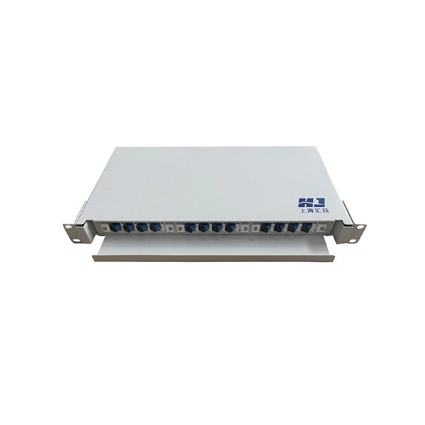
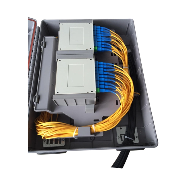
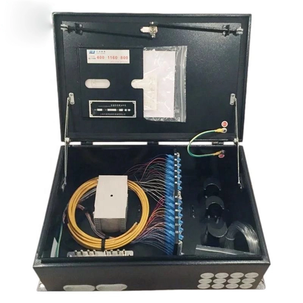
First, connect each pre-terminated fiber optic cable to the adapter panel separately, making sure the ports correspond one-to-one; then fix the fiber optic adapter panel to the front panel of the distribution box with the bend radius control clip. In general, installing the optical fiber distribution box can be divided into three steps: installing the optical fiber distribution box on the rack, introducing the optical cable into the optical fiber distribution box, and planning the optical fiber path in the optical fiber distribution box. The. Bottom installation: Select a proper installation position in the equipment room and drill four holes in the floor according to the dimensions shown in the manual. Fix the rack to the ground with expansion bolts. Top installation: Dimensions of four connection holes on the top according to the. The Optical Distribution Box (ODB) is high-density 2-in-2-out fiber box solution. Designing with a compact size of 340x220x100mm, the cabinet accommodates 1x2,1x4,1x8 and 1x16 etc. The 4 ports are sized for main cable from 9 to 16mm in diameter, along with 16 3mm cables. Accessory Kits:. Install the optical fiber distribution box on the rack. Ensure that the box is installed firmly and horizontally, and the deviation of perpendicularity is not greater than 3mm.
[PDF]
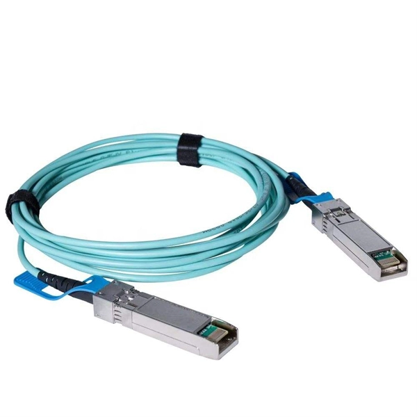
No, a 10G SFP (Small Form-factor Pluggable) module is designed to operate at 10 Gigabits per second (Gbps) and is not compatible with a 1 Gigabit per second (Gb) port. Therefore, a 10G SFP module will not work. When SFP optical module is inserted into the SFP port of Gigabit switch with fiber optic patch cable or copper cable, it can realize different distance transmission. For example, the maximum transmission distance is 160 km when using SFP1G-ZXC-55 optical module and LC duplex fiber patch cable, and. 10 Gigabit Ethernet (10GE, 10GbE, or 10 GigE) is a group of computer networking technologies for transmitting Ethernet frames at a rate of 10 gigabits per second. It was first defined by the IEEE 802. For example, when using the AE-SFP-ZX160 optical module and LC duplex fiber optic patch cords, the maximum transmission. Can 1G SFP optics work with 10Gb SFP+ ports on a 10Gb switch, or vice versa? This comprehensive guide reveals the intricacies of SFP and SFP+ compatibility and provides useful solutions for network switch users. Can 1G SFP Optics Run at 10G SFP+ Port? Can 10G SFP+ Optics Run at 1G SFP Port? Can. Small form-factor pluggable or SFP Modules can be described as compact and hot-pluggable hardware that connects various networking devices such as servers, routers, and switches. Networking standards, including Ethernet, Fiber Channel, and SONET, are also used with the SFP modules, broadening their.
[PDF]