An optical power meter (OPM) is a device used to measure the power in an signal. The term usually refers to a device for testing average power in systems. Other general purpose light power measuring devices are usually called,, power meters (can be sensors or ), or lux meters. A typical optical power meter consists of a , measuring and display. The sens.
[PDF]

Optical power meters can measure the power of both single-mode and multimode fibers. In single-mode fiber, the rays travel down its entire length without any internal reflection at all. In multimode fiber, multiple rays enter at different angles and possibly have different wavelengths. An optical power meter (OPM) is a device used to measure the power in an optical signal. The term usually refers to a device for testing average power in fiber optic systems. The term "optical power meter" may sound generic, but in popular usage, it specifically implies a fiber optic power meter. For light power measurements outside the field of. Optical loss is measured in “dB” which is a relative measurement, while absolute optical power is measured in “dBm,” which is dB relative to 1mw optical power Loss is a negative number (like –3. It details the main components, including sensor heads and display units, and explains the two primary sensor technologies: robust thermal sensors for high powers and. The OMM-6810B is a power and wavelength meter capable of simultaneously measuring the optical power and wavelength of a laser source. A wide variety of measurement heads cover wavelength ranges from 400 to 1650 nm for power ranges of up to +40dBm or 10W. Fiber optic connections form the backbone of modern data infrastructure, yet even a small speck of dust can render a link completely.
[PDF]

The mechanical dimensions of an optical power sensor can be quite relevant for applications, e.g. when a sensor needs to be temporarily inserted into some beam path, where there is little available space. There are some very flat hand-he. The mechanical dimensions of an optical power sensor can be quite relevant for applications, e.g. when a sensor needs to be temporarily inserted into some beam path, where there is little available space. There are some very flat hand-held sensors, mostly based on photodiodes, which require quite little space. Thermal power sensors are intrinsically relatively slow – particularly those for high powers, where the thermal capacity of the sensor is tentatively higher. Typical response times are of the order of 0.2 s to 2 s. Even photodiode-based power meters are normally not made very fast, since one could anyway not read a display which is updated e.g. 10. Power meters require some electrical power, which may either be provided with an external power supply or with batteries (which are normally rechargeable). Battery-powered operation is of course convenient by eliminating another cable enter the requirement of a nearby power socket, but on the other hand the need for regular recharging can also be i.
[PDF]
Multimode fiber optic cable has a larger core, typically 50 or 62. 5 microns that enables multiple light modes to be propagated. Because of this, more data can pass through the multimode fiber core at a given time. The maximum transmission distance for MMF cable is around 550m at the speed of. Multimode Fiber (MMF) has a core diameter, typically 50–100 micrometers, has ability to transfer multiple modes of light through the fiber core, uses lower-cost electronics (LED, VCSEL) operates at the 850 nm and 1300 nm wavelength and is used for short distance interconnections (up to 550m). This Applications Engineering Note (AE Note) discusses the criteria for properly selecting the optimal multimode fiber (MMF) for enterprise applications. Both fiber types play essential roles in today's optical.
[PDF]

Optical fiber cables consist of several key components, including the core, cladding, coating, strengthening fibers, and outer jacket, each essential for effective data transmission. Communication optical cable is a common wiring product. You should choose according to the nature of the specific project. Communication cable structure cable core Cable core: It is located in the center of the optical cable and. A TOSLINK optical fiber cable with a clear jacket. These cables are used mainly for digital audio connections between devices. A fiber-optic cable, also known as an optical-fiber cable, is an assembly similar to an electrical cable but containing one or more optical fibers that are used to carry. An optical fiber cable is a complex structure designed to protect fragile glass fibers that transmit digital data using light signals. This advanced cabling solution allows fast, secure data transfer and telecom over long distances. Understanding the components within a fiber optic cable enables. This series of courses are based on the Navy Electricity and Electronics Training Series (NEETS) section on Fiber Optic cable systems. The NEETS series is produced by the Naval Education and. This Lesson Learned is based on Maintainability Technique number OPS-08 from NASA Technical Memorandum 4628, Recommended Techniques for Effective Maintainability. It then discusses the history of optical fibers and their structure.
[PDF]
GPON is an alternative to Ethernet switching in campus networking. GPON replaces the traditional three-tier Ethernet design with a two-tier optic network which eliminates access and distribution Etherne.
[PDF]

The receiver of an optical module has an overload point. Therefore, an optical attenuator is required to reduce the optical power. By introducing a precise and constant amount of optical loss, it ensures that the incoming signal remains within the optimal operating range of the receiver. A. Average optical power refers to the optical power outputted by the optical module's transmitter under normal working conditions, which can be understood as the intensity of light. The transmitted optical power is related to the proportion of "1"s in the transmitted data signal; the more "1"s, the. The receiver of an optical module has an overload point. If the optical power received by the receiver is excessively high, the optical module will be burnt. In addition, during signal transmission in a WDM system, the. 📦 For purchasing, use the RP Photonics Buyer's Guide for optical attenuators. It provides an expert-curated supplier directory, buyer-focused technical background information, and structured selection criteria to support professional procurement decisions. Optical attenuators are devices that. An optical attenuator, or fiber optic attenuator, is a device used to reduce the power level of an optical signal, either in free space or in an optical fiber. Optical internetworks are data networks composed of routers and data.
[PDF]

Shop DigiKey's large in-stock selection of Fiber Optic Attenuators. View inventory, pricing and order now for same day shipping!. Use this optical attenuators buying guide to compare major types, define selection criteria, and find suppliers: 🔬 Encyclopedia article: optical attenuators 📦 Top-level product category: optical components and devices Click on a logo to get to the details of that supplier's offer. Our list of. Keysight optical attenuators provide precise control of optical signal power for accurate and repeatable optical component testing. Attenuators emulate signal loss, balance power levels, and protect sensitive devices during testing. Keysight attenuators offer low insertion loss, low. Attenuators from VIAVI offer a complete range of power-balancing options, from fixed to variable optical attenuators in field, lab, and manufacturing environments. VIAVI offers the industry's most complete range of optical attenuators for installation and maintenance of singlemode and multimode. Fiber optic attenuators are devices used to reduce or monitor the power level of a fiber optic signal. Basic types of fixed attenuation include single mode, dual window and multimode in D4/PC, FC, FC/UPC, MU, SC, SC/APC and UPC, ST and ST/UPC style connectors. Optical attenuators usually work by. FS fixed and variable fiber optic attenuators with leading attenuating fibers guarantee consistent and stable fiber attenuation (0~60dB) in WDM transmission.
[PDF]
An optical power meter (OPM) is a device used to measure the power in an signal. The term usually refers to a device for testing average power in systems. Other general purpose light power measuring devices are usually called,, power meters (can be sensors or ), or lux meters. A typical optical power meter consists of a , measuring and display. The sens.
[PDF]

Mechanical Optical Switches: Switching times typically range from 1-10ms, suitable for long-distance transmission scenarios where latency is not critical (such as backbone network protection switching). Solid-State Optical Switches: Based on thermooptic or electrooptic effects, response. We lead the industry in optical switch technology, delivering the lowest insertion loss (0. 2 dB), fastest switching speed (10 ns), broadest wavelength range (300–2400 nm), widest fiber compatibility, highest optical power handling (50 W), and space-qualified reliability. Backed by over 25 years of. Use this optical switches buying guide to compare major types, define selection criteria, and find suppliers: Professional purchasing of high-value photonics products is a substantial responsibility, where a structured decision-making process is essential. RP Photonics offers a lot of help: Get. This document is a troubleshooting and selection guide for common optical switch failures, compiled based on over 500 field cases. These switches are built on proven, reliable optomechanical technology that has seen more than 30 years of successful operation. Each. The POLATIS ® Series 7000 384x384 all-optical circuit switch is designed to meet the most demanding applications with exceptionally low optical loss, compact size, and fast switching speeds. With support for Software-Defined Networks (SDNs) via embedded NETCONF and RESTCONF control interfaces, the.
[PDF]

In this paper, various operational factors affecting 100G transmission over G. D fiber-cables are discussed to make the right fiber selection for the long-haul network. Selecting appropriate G. 652 fibre was originally optimized for use in the 1310 nm wavelength region but can also be used in the 1550 nm region. This is the latest revision of a Recommendation that was first created in 1984 and deals with some relatively minor modifications. a number of concatenated cable. G. 92% of. Fiber optic cables are the ultimate technology used in data transfer using light waves. They are classified based on wavelength band, core/cladding size, application, and compliance with international standards such as IEC, ITU-T, and TIE/EIA. In the next sections, the real artwork is putting on. This guide explains the most important ITU-T G. 655—to help you make an informed decision for your project, whether it's a long-haul backbone or a final FTTH drop. In the world of fiber optics, not all glass is created equal. The core of every cable—the optical. Because GPON and XGS-PON are deployed in diverse environments, fiber-containing components such as PLC splitters must be evaluated not only by their standard parameters but also by their sensitivity to bending loss, which is critical for maintaining stable optical transmission. The ITU-T defines.
[PDF]
An increasingly common special-purpose OPM, commonly called a "PON Power Meter" is designed to hook into a live PON () circuit, and simultaneously test the optical power in different directions and wavelengths. This unit is essentially a triple power meter, with a collection of wavelength filters and optical couplers. Proper calibration is complicated by the varying duty cycle of the measured optical signals. It may have a simple pass/ fail display, to facilitate easy use by operators wit.
[PDF]
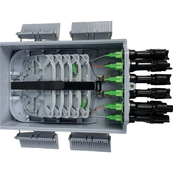
PLC optical splitters (planar waveguide optical splitter) is a key component in optical fiber communication networks and is widely used in optical fiber distribution systems such as FTTH (fiber to the home) and PON (passive optical network). PLC (Planar Lightwave Circuit) splitters are crucial components in optical networks, facilitating the distribution of optical signals to multiple destinations. This article provides a comprehensive understanding of PLC splitters, including their working principle, types, advantages, deployment. PLC splitter, also called Planar Waveguide Circuit splitter, is a device used to divide one or two light beams into multiple light beams uniformly or combine multiple light beams to one or two light beams.
[PDF]