
An optical receiver is an electronic device that detects and converts optical signals into electrical signals. The primary function of an optical receiver in digital TV setups is to facilitate the transmission of high-quality audio signals between. In this architecture, optical fiber carries signals from the headend to distribution nodes across long distances, after which coaxial cable completes the final delivery to subscribers. He oversaw the day-to-day operations of the site to ensure readers have the most up-to-date information on everything from operating systems to gadgets. Prior to his current. othing beats surround sound for movies and TV — and surround sound starts with a home theater receiver. But a receiver can give you a lot more than that. During my time as a Crutchfield Sales Advisor, I helped many people choose the receiver that worked best for them. They are a step above the previously used analog audio outs. The most common types are optical and coaxial. The rest of this article will delve into how digital audio output works, how its types differ, and. When it comes to enhancing your home entertainment experience, connecting your optical TV cable to your home theater system is an essential step that can significantly elevate your audio-visual enjoyment. This guide will walk you through the process in detail, ensuring that you have all the.
[PDF]

DFM in optical design refers to the process of designing optical components and systems that are manufacturable, testable, and inspectable. The importance of DFM lies in its ability to reduce production costs, improve product quality, and accelerate time-to-market. The SPIE Digital Library's coverage of design for manufacturability (DFM) predominantly centers on semiconductor and optical system manufacturing. The content heavily emphasizes photolithography-related DFM, detailing techniques for optimizing mask designs, optical proximity correction, and. Design for manufacturability (DFM) is a critical first step in the development of any optical component. In the context of optics, DFM involves optimizing the design of optical components and systems to minimize production costs, reduce. Optical assembly manufacturing combines precision components such as lenses, prisms, mirrors, and other components that must perform in demanding environments. Taking complex optical systems from simulation into production involves meeting a range of mechanical, functional, and other requirements. Today, we are expanding my very first blogpost from 2020 and discussing the concept of Design for Manufacturability (DFM). In this article, we explore why DFM matters and how key design aspects influence the success of plastic optics. Understand the Limitations of Injection Molding.
[PDF]

Optical attenuators use several principles in order to accomplish the desired power reduction. The types of attenuators generally used are fixed, stepwise variable, and. An optical attenuator is a passive device that is used to reduce the power level of an optical signal. The attenuator circuit will allow a known source of power to be reduced by a predetermined factor, which is usually expressed as decibels. Key requirements include minimal effect on the beam profile, low wavelength and polarization dependence, and sufficient power handling capability. The basic types of optical attenuators are fixed, step-wise variable, and continuously variable. Since too much light may saturate the fiber optic receiver, optical attenuators are often deployed in the system to reduce the light power and achieve the best fiber. An attenuator is a device designed to reduce the intensity of electrical and electromagnetic oscillations smoothly, stepwise, or at a fixed rate. It primarily ensures the power or amplitude of a signal is lowered without significantly distorting its waveform. Attenuators are extensively used across.
[PDF]
When it comes to testing fiber optic cables, a Visual Fault Locator (VFL) is an essential tool in your toolkit. A VFL is used to detect faults, breaks, or bends in fiber optic cables by emitting a bright red light that is visible even through the fiber's jacket. Let's dive into everything you need to know about mastering VFLs. In the. Finding a break in a fiber optic cable can be challenging but is essential for maintaining a stable network. Common Indicators of a Cable Break Signal. Here Kingfisher's experienced engineers share their experience in best practices and procedures for fiber optic testing related mostly to installation and maintenance. We hope that by sharing our knowledge, we will help grow our industry. Please enjoy & pass on these notes. The following are key methods and techniques used for optical fiber cable line failure positioning: Visual Inspection: Perform a visual inspection of the. Locating faults in fiber optic cables requires specialized tools and techniques. Look for dirt, scratches, or damage on the connectors. Clean. To ensure the quality and continuity of fiber optic services, it is essential to identify and locate fiber optic cable faults as quickly and accurately as possible. In this article, you will learn about some of the common methods and tools for fiber optic testing and troubleshooting.
[PDF]

This procurement guide curates leading SFP module manufacturers and suppliers in Europe, summarizes their differentiators, and offers practical buying tips. ESTEL designs and manufactures high‑performance optical transceivers in Europe and in the US, with local technical support and a secure supply chain. Our optical modules power demanding telecom and datacom networks across data centers, metro and long‑haul links. Browse optical transceivers Talk to. Transceiver stands for Transmitter/Receiver Module. These (opto-)electronic devices allow data transmission over copper and fiber cables. A wide range of form factors are available allowing data rates from 100Mbps up to 800Gbps. Skylane Optics offers the full range of transceivers with an unique. We are committed to providing high-performing optics and transceivers through professional and reliable capabilities. Equipped with the most extensive and stringent testing and solution designing processes. Delivered fast, tested, and 100% compatible with your hardware. Swedish Telecom Opto is built for scale — not single-click sales. We work with mid to large organizations, supporting. There are 317 Optical Products Manufacturers in Southern Europe as of August 15, 2024; which is an 1. 26% increase from 2023. With over two decades of experience in the industry, we specialize in designing and producing high-quality optical components for a wide range of applications. Our team of skilled engineers and technicians are.
[PDF]

See the plans and pricing for routers for your home or business. Discover the cutting-edge technology of optical routers, designed to enhance your network's performance and efficiency. These advanced devices utilize light-based transmission for faster data transfer, reduced latency, and improved bandwidth. Explore how optical routers can revolutionize your. MikroTik hEX series router, specifically the hEX S model (RB760iGS). This device is a five-port. Features extends the transmission range of hdmi, ir and rs-232 signals using one fiber optic. Product Features ● High-speed GPON connectivity ensuring stable and reliable performance. Zte. For enquiries on SWIFT Microwave or SWIFT Fibre or to discuss your personal network requirement, click here for our service request form or please call us on 01-7100076, 08077265615 or e-mail enterprisesales@swiftng. net. The Connectivity Router - your best companion when it comes to SFP, SFP+ and SFP28 management! 1, 10 and 25 Gbps ports in a single device to make your life easier. ” mindset can be very helpful, but sometimes you simply need a device that works and solves the problem. Variety: TP-Link routers are available in different models and class. They vary in connectivity rate, which means you can get a model with the exact requirement you need. You can get one for as low as N14, 000 and as high as over N75, 000. iTEC Itec 18" Rechargeable Stand Fan (znx-item-00104. Andrakk 16inches.
[PDF]

Do you need a reliable, durable, and easy-to-install solution for your fiber optic cables? You're in the right place! Our product, consisting of a stainless steel wire and a reinforced nylon body, is specially designed for drop cables with diameters up to 3-8mm. ADSS Anchor Tension Clamps are hardware fittings used to securely terminate and anchor ADSS fiber optic cables on poles or towers without damaging the cable. They are lightweight and economical, allowing for easy installation, and suitable where environmental performance is low. At the same time, the plastic is thick enough not to break within the studied period, making it ideal for. In 2015, Jera line started to produce clamps and brackets for FTTX fiber optic cable deployment. With a combination of stainless steel wire and reinforced nylon body, Fibeye tension clamps offer excellent durability and performance. Do you need a reliable, durable, and. MefiberOptic. com provide a complete solution of products for fiber optic cable deployment for FTTx network constructions. We supply various clamps and brackets for ADSS or drop cable install solutions. Jera is. Each accessory serves a specific purpose: fiber tension clamps provide the right tension without damaging cables, drop wire clamps secure cables in outdoor environments, and anchor hooks and brackets support and stabilize cables on poles, walls, or buildings. Together, these accessories ensure that.
[PDF]

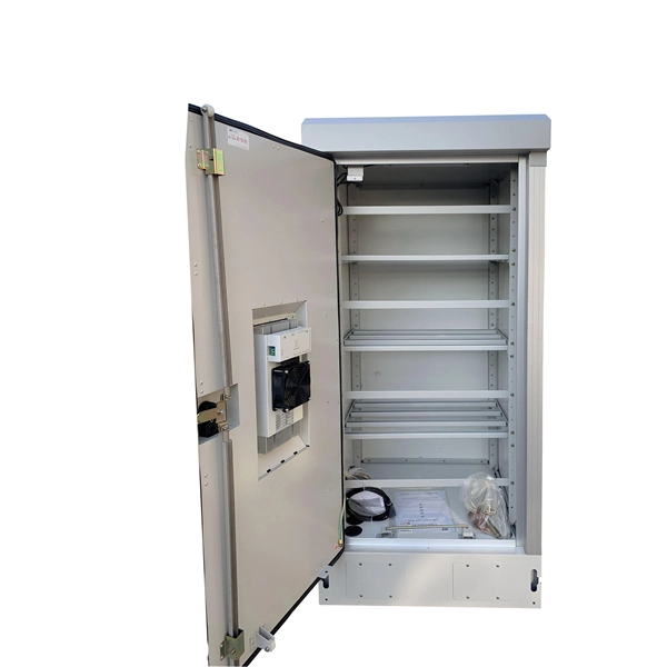
First, connect each pre-terminated fiber optic cable to the adapter panel separately, making sure the ports correspond one-to-one; then fix the fiber optic adapter panel to the front panel of the distribution box with the bend radius control clip. In general, installing the optical fiber distribution box can be divided into three steps: installing the optical fiber distribution box on the rack, introducing the optical cable into the optical fiber distribution box, and planning the optical fiber path in the optical fiber distribution box. The. Bottom installation: Select a proper installation position in the equipment room and drill four holes in the floor according to the dimensions shown in the manual. Fix the rack to the ground with expansion bolts. Top installation: Dimensions of four connection holes on the top according to the. The Optical Distribution Box (ODB) is high-density 2-in-2-out fiber box solution. Designing with a compact size of 340x220x100mm, the cabinet accommodates 1x2,1x4,1x8 and 1x16 etc. The 4 ports are sized for main cable from 9 to 16mm in diameter, along with 16 3mm cables. Accessory Kits:. Install the optical fiber distribution box on the rack. Ensure that the box is installed firmly and horizontally, and the deviation of perpendicularity is not greater than 3mm.
[PDF]

RFP Publishing Period: from November 12th, 2025 to 14h00, November 26th, 2025 (GMT+6:30), during MYTEL's office hours — from 8h00 to 17h30, Monday to Friday. 61-63, Zoological Garden Rd., Dagon Township, Yangon, Myanmar. We have identified 63 global optical fibre cable tenders from the public procurement domain worldwide. View the latest global tenders for optical fibre cable from Africa, the Americas, Asia, Australia, Europe, the Middle East, and other countries. Find global tender information, RFPs, RFQs, ICBs. Mytel Announcement on Invitation to Bidding No. RFP 134/2025/MYTEL-OPTICALCABLE – “Purchase OPTICAL CABLE for Mytel”. Requesting Party: TELECOM INTERNATIONAL MYANMAR CO., LTD. Tender For Provision of Fiber-optic internet services for OCHA in Sudan., communication channel rental services (fiber-optic communication channel rental services in the city of makinsk. Please click here to see the Current Opportunities. Procurement of Furniture and Equipment for the support to operationalize Public Procurement Act. Are you searching for the latest Fiber Optic Cable Tenders from trusted sources across the globe? Tender Impulse is the go-to tender website for businesses seeking verified and timely updates on public tenders, government tenders, and business tenders in a wide range of sectors.
[PDF]
No, a 10G SFP (Small Form-factor Pluggable) module is designed to operate at 10 Gigabits per second (Gbps) and is not compatible with a 1 Gigabit per second (Gb) port. Therefore, a 10G SFP module will not work. When SFP optical module is inserted into the SFP port of Gigabit switch with fiber optic patch cable or copper cable, it can realize different distance transmission. For example, the maximum transmission distance is 160 km when using SFP1G-ZXC-55 optical module and LC duplex fiber patch cable, and. 10 Gigabit Ethernet (10GE, 10GbE, or 10 GigE) is a group of computer networking technologies for transmitting Ethernet frames at a rate of 10 gigabits per second. It was first defined by the IEEE 802. For example, when using the AE-SFP-ZX160 optical module and LC duplex fiber optic patch cords, the maximum transmission. Can 1G SFP optics work with 10Gb SFP+ ports on a 10Gb switch, or vice versa? This comprehensive guide reveals the intricacies of SFP and SFP+ compatibility and provides useful solutions for network switch users. Can 1G SFP Optics Run at 10G SFP+ Port? Can 10G SFP+ Optics Run at 1G SFP Port? Can. Small form-factor pluggable or SFP Modules can be described as compact and hot-pluggable hardware that connects various networking devices such as servers, routers, and switches. Networking standards, including Ethernet, Fiber Channel, and SONET, are also used with the SFP modules, broadening their.
[PDF]

The solution is to unplug the fiber and reinsert it into the SFP module interface until a “click” sound is heard, indicating the fiber connector and SFP module are properly connected. Contamination or damage on the fiber end face requires the use of a fiber end-face inspection. The physics of noise in optical communication links is of great interest in the design of fiber optic communication systems. The origins of noise in. Optical transceivers—such as SFP, QSFP, and OSFP transceivers —are essential components in high-speed data center and enterprise networks. These fiber optical transceivers convert electrical signals into light and back, enabling long-range, high-bandwidth communication over fiber optic links. Think of it. Optical transmission is vulnerable to various sources of signal degradation, including chromatic dispersion, modal dispersion, polarization mode dispersion, and noise. In the real world, an optical receiver's ability to resolve information is impacted by the presence of noise. They are the foundation of the network world. SFP optical modules are precision devices, and various faults may inevitably occur during operation. These faults can. Noise and Signal Interference in Optical Fiber Transmission Systems is a compendium on specific topics within optical fiber transmission and the optimization process of the system design. It offers comprehensive treatment of noise and intersymbol interference (ISI) components affecting optical.
[PDF]

Managing optical attenuation helps keep your signal safe. Clean your optical connectors so you do not lose. Optical Signal Attenuation is the single greatest factor limiting the distance and performance of your network. Understanding it is crucial for anyone involved in data centers, telecommunications, or enterprise networking. This guide will demystify signal loss, explore its causes, and show you how. In high-speed environments, where the optical link budget is measured in fractions of a decibel, diagnosing and eliminating unexpected loss is the network engineer's most critical task. This field guide provides a systematic, step-by-step approach to troubleshooting and resolving the most common. Signal loss in Fiber Optic networks can make data slow. It can also break your connection. You should fix it fast to get speed and stability back. > You can solve this with simple steps. Signal Degradation (Loss of Light) When the signal quality degrades, it could be a sign of attenuation or excessive loss in the system. The signal might become weaker, resulting in slower speeds or dropped connections. -. Fiber optic networks are celebrated for their speed and reliability, but even the best systems can encounter problems. When issues like signal loss, slow speeds, or intermittent connectivity arise, systematic troubleshooting is key. Things like impurities in the fiber core and reflections at the core-cladding edge cause this drop.
[PDF]

On average, you can rent a Fusion Splicer for $275/day, $773/week, $1424/month. The price of these splicers can be higher because of their mechanical complexity and ability to handle various fiber types, including large-core fibers. Hybrid splicers bring in various features that are present in both automatic splicers and manual splicers. They can be aligned by the core. Fiber optic fusion splicers are critical tools for deploying and maintaining fiber networks, with significant variations in performance, features, and pricing. This guide breaks down the key cost-influencing factors across five dimensions—splicer types, technology, performance, accessories, and. A fiber optic splicing machine is a specialized machine used to fuse two optical fibers together to form one long one. The machine, also known as a fiber optic fusion splicer, uses electricity to melt the two optic cables into one. The fiber fusion splicer conducts the fusion with high accuracy to. Check each product page for other buying options. Get reliable equipment with fast splicing times and comprehensive accessories included. It features a mini handheld design, integrated buttons and touch screen, simple operation, low.
[PDF]