Based on analysis on the dispersion of the optical system of a MEMS-based VOA, we provide a method to reduce the WDL significantly with minor revision on the end-face angle of the collimating lens. 📦 For purchasing, use the RP Photonics Buyer's Guide for variable optical attenuators. It provides an expert-curated supplier directory, buyer-focused technical background information, and structured selection criteria to support professional procurement decisions. Variable optical attenuators are. An optical attenuator, or fiber optic attenuator, is a device used to reduce the power level of an optical signal, either in free space or in an optical fiber. The basic types of optical attenuators are fixed, step-wise variable, and continuously variable. Optical attenuators are commonly used in. Applications in broadband optical fiber communication system need variable optical attenuators (VOAs) with low wavelength-dependent loss (WDL). What Are Fiber Optic Attenuators? Fiber optic attenuators, also called optical attenuators, are passive. Optical attenuators are categorized based on their attenuation mechanism and adjustability: Fixed Optical Attenuators: These attenuators reduce the signal power by a predetermined value and are used in applications where a constant level of attenuation is required. It works by dissipating a portion of the optical power passing through it, thereby lowering the overall power level. Fiber optic attenuators.
[PDF]
You can plug various networking devices into an SFP (Small Form-factor Pluggable) port, such as fiber optic transceivers, gigabit Ethernet modules, and SFP modules. These can include devices such as switches, routers, network interface cards, and media converters. SFP (Small Form-factor Pluggable) is a compact, hot-pluggable network interface module used to connect network devices (switches, routers, firewalls) to fiber optic or copper cables. An SFP interface on networking hardware is a modular slot for a media-specific transceiver, such as for a fiber-optic cable or a copper. Optical transceivers are compact, hot-pluggable devices that convert electrical signals into optical signals, enabling high-speed data transmission across switches, routers, and other networking equipment. Transceiver compatibility is a key concern in enterprise network deployments. Can the sfp interface be plugged. SFP modules function by converting electrical signals from a switch or router into optical or copper signals that can travel through various transmission media. They are inserted into SFP ports found on networking hardware and come in multiple variants to support different cable types, distances.
[PDF]

This SFP module provides 20km transmission distance over single-mode fiber at a nominal wavelength of 1310nm. The transmitter section uses a 1310nm FP laser that is a class 1 laser compliant according to International Safety Standard IEC 60825. A 1310nm optical module lets you move data efficiently through fiber optic communication networks. As part of the O-band (1260–1360 nm), it balances low dispersion, stable performance, and cost efficiency. This makes it widely adopted in data centers, enterprise backbones, and metro access. The transmission distance of optical modules is divided into short distance, medium distance, and long distance. Transmission distances greater than or equal to 30km are considered long-distance transmissions. Light commonly used in optical fiber is 850nm. The GPON OLT SFP transceiver provides an asymmetric 1. 244Gbps upstream and 2. 488Gbps downstream, reaching a link up to 20km over SMF via SC/UPC connector. It can operate at temperatures between -40°C and 85°C. Digital optical monitoring (DOM) support is also present to allow access to real-time.
[PDF]

When it comes to testing fiber optic cables, a Visual Fault Locator (VFL) is an essential tool in your toolkit. A VFL is used to detect faults, breaks, or bends in fiber optic cables by emitting a bright red light that is visible even through the fiber's jacket. Let's dive into everything you need to know about mastering VFLs. It's a cost-effective and. Visual Fault Locator (VFL) testing is one of the most fundamental inspection methods used in FTTH, ODN, and data center environments. A VFL emits a visible red laser (typically 650 nm) that travels along the fiber core and leaks out at points of excessive loss, fiber breaks, or microbends. Although. The Fiber Visual Fault Locator Kit is an essential tool for network technicians and engineers; it provides an accurate and quick method of finding such problems as breaks, bends or faults that may affect the network's operation. It works by injecting a visible red laser light (usually in the 650nm wavelength) into the fiber. When the light encounters a fault, such as a break, bend, or bad splice, it leaks out of the fiber, making the. Conducting efficient, repeatable fiber optic cable certification requires an array of specialized test equipment: Optical Loss Test Set (OLTS) – Integrates adjustable light source and power meter for efficient, Tier-1 insertion loss testing. Visual Fault Locators – Handheld devices projecting.
[PDF]

Insertion loss tells you how much weaker the signal becomes after passing through the splitter. Let's say you have a laser output at 0 dBm (which is 1 milliwatt of optical power). If you use a 1×8 splitter with ~10. 5 dB of insertion loss, the power at each output would be: 0 dBm – 10. 5. Enter excess loss from the splitter datasheet for your wavelength. Add connector and splice quantities with realistic planning losses. Include any additional component losses and an engineering margin. Enable power budget to estimate received power and margin. Press Calculate to show results above. Understanding optical splitter loss isn't just about plugging numbers into a calculator. It's about knowing what factors contribute to that loss, how manufacturers specify it, and how it impacts the overall performance and reach of your network. Ignore it, and you might find your signal too weak to. Optical insertion loss refers to the signal loss resulting from the insertion of components such as connectors or splices in an optical fiber system. Common ratios: For cascades, add losses and validate margin using the Optical Budget tool. This Fiber Optic Splitter Insertion Loss is the splitter devices loss, Considering fiber connectors or connectors+adapter insertion loss in LGX, The fiber splitter IL would be a little bigger. To make clear the basic ftth fiber splitter loss in performance, You can refer to the below loss chart.
[PDF]
The table below is a Cross Reference for all Palo Alto Networks Hardware Accessories and includes the Palo Alto Networks SKU, RoHS Compliance, Harmonized Tariff Schedule, ECCN and License information. Choose an option Alt text (alternative text) helps when people can't see the image or when it doesn't load. Aim for 1-2 sentences that describe the subject, setting, or actions. This is used for ornamental images, like borders or watermarks. Short description for people who can't see the image or. The merchandise under consideration is an optical transceiver, part# EOLP-1396-10-X. This item is a single mode transceiver in a small form-factor pluggable (SFP) module for serial optical data communications with an operating data rate of 11. 3Gbps and transmission distance of up to 10 km. The. Currently, the U. import Harmonized Tariff Schedule (HTS) code for optical modules is 8517. HTS website https://hts. gov/,searching for "8517. 00" shows the result "General Free1/", which indicates that attention should be paid to 9903. All parts listed below are RoHS compliant and meet the requirements of the current RoHS 2. How to Reduce Optical Module Costs | SFP & QSFP Cost Optimization Guide-Industry News-Sate Optics-Network Connectivity Solutions! In today's rapidly evolving network environments, reducing operational costs is a top priority for data centers, telecom operators, and system integrators.
[PDF]

FTTP ONT red light often indicates optical signal loss or fiber cable connection issues. First, check the fiber optic cable for bends, damage, or loose connections at the. An optical audio cable should have a red light at each of the connectors when it's in place and working correctly. If you don't see the light at either of the ends, the cable isn't connected properly, is broken, or you might just have a faulty cable. The light is an indicator of a problem, rather. Customer: The power light is green, the optical light is red, and the UNI-D 1 port is orange. Credit: Jim Gensheimer for Stanford University Light does a lot of work in the modern world, enabling all types of information technology, from TVs to satellites to fiber-optic cables that carry. An optical amplifier is a device which receives some input signal light and generates an output signal with higher optical power. Typically, inputs and outputs are laser beams (very rarely other types of light beams), either propagating as Gaussian beams in free space or in a fiber. The. An optical amplifier is a device that amplifies an optical signal directly, without the need to first convert it to an electrical signal. I'm just wondering because I had a fiber optic cable plugged in and pulled it out while using it and just hoping that didn't cause some issue. Most optical outs are.
[PDF]

Nigeria Sfp Optical Module Suppliers Directory provides list of Nigeria Sfp Optical Module Suppliers & Exporters who wanted to export sfp optical module from Nigeria. Don't know your target market? Wanted to market your Sfp . The Cisco SFP 10G SR module is meant to provide data transfer at 10Gbps speed with short-range. Qsfp-100g-sr4-s 100g sfp module s-class qsfp-100g-sr4-s 100gbase sr4 qsfp transceiver, mpo, 100m. Small Form-factor Pluggable (SFP) is a compact, hot-pluggable network interface module format used. The best choice is Cisco SFP Transceivers are the best in offering high performance and flexibility in the enterprise and data center networking. The hot-swap modules offer speeds of 1G, 10G, 25G, 40G, and 100G and will smoothly scale to various networking requirements. They come in SFP+, SFP. Fiber optic transceivers are widely used in telecommunication, CATV, FTTx, and various kinds of other data communications. Their commitment to high-quality service and tailored recommendations can support organizations looking to enhance their digital operations. Do You Really Know Where Your Transceivers Come From? Factory-direct optical transceivers and high-speed cables, from legacy links to 1. 6T, built to deploy faster, scale cleaner, and stay compatible as your network evolves. At scale, the biggest problems come from what you don't control, not what.
[PDF]

Based on the need for real-time sag monitoring of Overhead Power Lines (OPL) for electricity transmission, this article presents the implementation of a hardware and software system for online monitoring of OPL cables. OptiSystem is an optical communication system simulation package for designing, testing, and optimizing virtually any type of optical link in the physical layer of a broad spectrum of optical networks, from analog video broadcasting systems to intercontinental backbones. A system-level simulator. Enhance your OTDR training and demonstrations with the portable Fiber Lab MSP. This all-in-one solution simulates P2P, FTTx, and Cell Tower fiber spans in a single unit, while including over 20km of fiber, good/bad splices, 1xN splitter, and reflective connectors. WHY CHOOSE THE FIBER LAB MSP? When. OCSim modules have been proven to provide accurate simulations. The modules which are continuously upgraded are and laboratory simulation experiments. The mathematical model based on differential equations and the methods of. This repository is a Python-based framework to simulate systems, subsystems, and components of fiber optic communication systems, for educational and research purposes. Several digital modulations available (M-PAM, square M-QAM, M-PSK, OOK) to simulate IM-DD and coherent optical systems.
[PDF]

See the plans and pricing for routers for your home or business. Discover the cutting-edge technology of optical routers, designed to enhance your network's performance and efficiency. These advanced devices utilize light-based transmission for faster data transfer, reduced latency, and improved bandwidth. Explore how optical routers can revolutionize your. MikroTik hEX series router, specifically the hEX S model (RB760iGS). This device is a five-port. Features extends the transmission range of hdmi, ir and rs-232 signals using one fiber optic. Product Features ● High-speed GPON connectivity ensuring stable and reliable performance. Zte. For enquiries on SWIFT Microwave or SWIFT Fibre or to discuss your personal network requirement, click here for our service request form or please call us on 01-7100076, 08077265615 or e-mail enterprisesales@swiftng. net. The Connectivity Router - your best companion when it comes to SFP, SFP+ and SFP28 management! 1, 10 and 25 Gbps ports in a single device to make your life easier. ” mindset can be very helpful, but sometimes you simply need a device that works and solves the problem. Variety: TP-Link routers are available in different models and class. They vary in connectivity rate, which means you can get a model with the exact requirement you need. You can get one for as low as N14, 000 and as high as over N75, 000. iTEC Itec 18" Rechargeable Stand Fan (znx-item-00104. Andrakk 16inches.
[PDF]

Urban Areas: 25–40m spacing (concrete poles, 10–12m height)., steel lattice structures). Factors: Cable weight (kg/km) Ice loading (up to 50mm. The Fiber Optic Association, Inc. (FOA) was founded in 1995 to help develop the workforce to build the fiber optic networks to support a rapid expansion in communications and the Internet. The charter of the FOA was to promote professionalism in fiber optics through education, certification, and. to n utral comm. cable R. FO-CS JOINT USE CLIMBING SPACE REQUIREMENTS 51. APPENDIX A - COVER SHEET / TOC 52. RUS DRAWING #PM12 58. CHECK. d suppliers of electrical construction services. They define a minimum baseline of quality and workmanshi for installing electrical products and systems. NEIS® are intended to be referenced in contrac documents for electrical construction ation or liability to users of this publication. Choose the type of pole The basic pole height is 7m and the tip diameter is 150mm. In case of special sections, crossing obstacles or roads or railways, the pole height of 8m, 9m, etc. can be selected. Cables 300 V or less need to be a minimum two feet over the street light. Climbing Space is an unobstructed, vertical space along the side or corner of the pole. In gen-eral, it consists of an imaginary box, 30-inches square, extending at least 40 inches above the highest communications cable or.
[PDF]
Cost ranges for a residential fiber optic cable run typically span from $1,000 to $12,000, with most projects landing in the $3,000–$8,000 band. The main drivers are trench depth and length, whether the line is buried or aerial, and the in-home termination requirements. The main cost drivers are materials, installation time, and environmental factors that affect trenching, conduit, and terminations. This article provides cost. Installing an optical fiber network is a significant investment that requires careful financial planning. Whether you're upgrading an existing system or starting from scratch, understanding the costs involved can help you allocate your budget wisely. This guide will walk you through the key factors. How Much Does Fiber Optic Cable Cost per Foot? On average, commercial projects range from $5,000 to $20,000 per mile underground and $40,000 to $60,000 per mile for aerial deployment. Individual business connections often cost between $15,000 and $30,000 for 100–200 network drops. Hiring. Homeowners typically pay a broad range for running fiber optic cable from the street to a residence, with the main cost drivers being trenching or aerial installations, cable material, labor time, and permit requirements. The price also varies by fiber type (GPON vs. The price or cost to install fiber reflects material choices, labor hours, and local regulations, with per-mile and per-ft metrics common in.
[PDF]

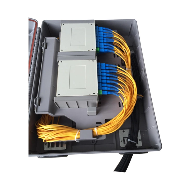
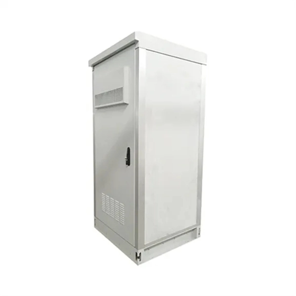
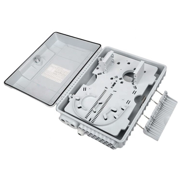
First, connect each pre-terminated fiber optic cable to the adapter panel separately, making sure the ports correspond one-to-one; then fix the fiber optic adapter panel to the front panel of the distribution box with the bend radius control clip. In general, installing the optical fiber distribution box can be divided into three steps: installing the optical fiber distribution box on the rack, introducing the optical cable into the optical fiber distribution box, and planning the optical fiber path in the optical fiber distribution box. The. Bottom installation: Select a proper installation position in the equipment room and drill four holes in the floor according to the dimensions shown in the manual. Fix the rack to the ground with expansion bolts. Top installation: Dimensions of four connection holes on the top according to the. The Optical Distribution Box (ODB) is high-density 2-in-2-out fiber box solution. Designing with a compact size of 340x220x100mm, the cabinet accommodates 1x2,1x4,1x8 and 1x16 etc. The 4 ports are sized for main cable from 9 to 16mm in diameter, along with 16 3mm cables. Accessory Kits:. Install the optical fiber distribution box on the rack. Ensure that the box is installed firmly and horizontally, and the deviation of perpendicularity is not greater than 3mm.
[PDF]