
ITU & IEC allow 0. 75 dB loss per mated pair. Splitter loss values are "Typical" and include a connector in and out. These values are approximate and should not be exceeded by more than 1-1. 5 dB, which could indicate dirty connectors, bad splices, or. ITU & IEC allow 0. These are known as passive optical splitters, and they perform the function. Let's start with the simplest part: the ideal, theoretical loss caused purely by dividing the light equally among N paths. This is often called Distribution Loss or Ideal Split Loss. Understanding the types of splitters, their impact on network performance, and how to measure their losses ensures high-quality network operation and facilitates optimal splitter selection based on. Use 2×N when two inputs feed the same distribution stage. Common values: 2, 4, 8, 16, 32, 64. Wavelength is recorded in outputs for documentation. 5 dB depending on splitter type. Fusion splices often plan around 0. Optional: patch. Excess loss is the ratio of the optical power launched at the input port of the splitter to the total optical power measured from all output ports. It assures that the total output is never as high as the input. Components, such as fiber cables, splitters, and switches, introduce attenuation. The maximum allowable distance between a transmitting laser and receiver is based upon.
[PDF]

Insertion loss tells you how much weaker the signal becomes after passing through the splitter. Let's say you have a laser output at 0 dBm (which is 1 milliwatt of optical power). If you use a 1×8 splitter with ~10. 5 dB of insertion loss, the power at each output would be: 0 dBm – 10. 5. Enter excess loss from the splitter datasheet for your wavelength. Add connector and splice quantities with realistic planning losses. Include any additional component losses and an engineering margin. Enable power budget to estimate received power and margin. Press Calculate to show results above. Understanding optical splitter loss isn't just about plugging numbers into a calculator. It's about knowing what factors contribute to that loss, how manufacturers specify it, and how it impacts the overall performance and reach of your network. Ignore it, and you might find your signal too weak to. Optical insertion loss refers to the signal loss resulting from the insertion of components such as connectors or splices in an optical fiber system. Common ratios: For cascades, add losses and validate margin using the Optical Budget tool. This Fiber Optic Splitter Insertion Loss is the splitter devices loss, Considering fiber connectors or connectors+adapter insertion loss in LGX, The fiber splitter IL would be a little bigger. To make clear the basic ftth fiber splitter loss in performance, You can refer to the below loss chart.
[PDF]

This article provides a detailed technical comparison between fiber optic and copper cables, offering a clear perspective for engineers, network architects, and procurement managers. The core distinction between the two technologies lies in the physics of data. However, the exponential growth in data demand has positioned fiber optic technology as the superior alternative for performance, scalability, and future-readiness., 10G/25G/40G/100G and beyond depending on optics and reach). Copper Ethernet scales too, but practical limits are lower and depend. The two main options are fiber optic cables and copper cables, each with its own advantages and drawbacks. Fiber optic cables are praised for their high performance and scalability, while copper cables remain a cost-effective choice, especially for budget-conscious projects and older systems. Copper wire is more susceptible to interference and has limited data capacity, making optical fiber the preferred choice for modern high-speed. Optical connectivity, utilizing fiber-optic technology, has emerged as the superior choice for modern networking, offering unparalleled performance, reliability, and scalability. For example, a typical 10 Gbps copper Ethernet link (such as Cat 6A) over 100 meters can consume approximately 5 to 8+.
[PDF]

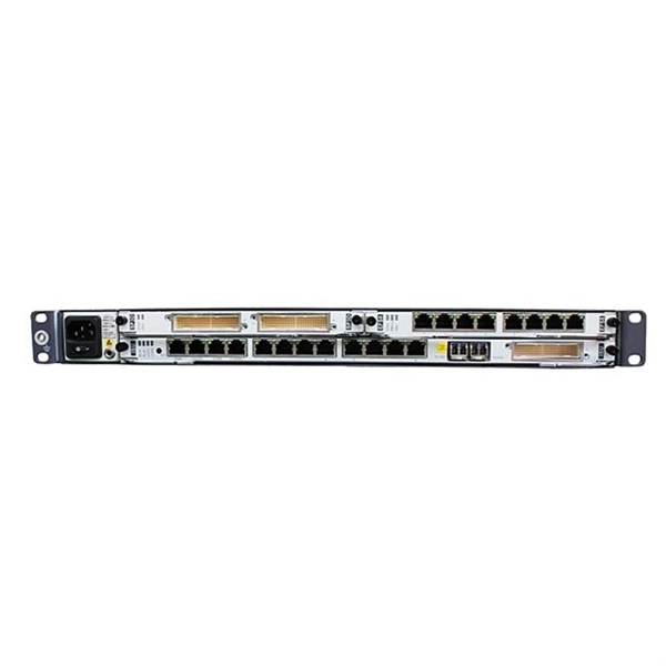
How to Connect Fiber Splitter & Configure ONU with OLT | Onu connected Vsol olt through splitter . more. How to Connect OLT and ONU Devices? To configure the ONU easily, it must first be connected to the OLT. more. The OLT communicates with the optical network unit (ONU) or optical network terminal (ONT) at the user end, coordinating the distribution of data and ensuring that each connected user receives the appropriate information. Equipment Components Generally speaking, OLT equipment includes a rack. FTTH (Fiber To The Home) is a technology that provides high-quality internet access directly to consumers' homes over an optical fiber infrastructure. This provides users with a dependable and high-speed network service and little to no wait times. This network is suitable for building. FTTH (Fiber-to-the-Home): This is a broadband network architecture where optical fiber runs directly to the customer's home, providing extremely high-speed internet, video, and voice services. OLT (Optical Line Terminal): The OLT is located at the service provider's central office or point of.
[PDF]

1 Overall Installation Diagrams 3. 3 Recommended Construction Procedure 3. 6 Example for Configuring Passive Ethernet All-Optical Networking 3. 1. With Huawei's core concept for ODN construction centering on full and dense coverage coupled with short and easy access, Huawei's ODN 3. 0 solution uses two transformative technologies to support five typical network scenarios. In the earliest FTTH solution, ODN 1. 0 optical splitting was used for. 3. 1 Overall Installation Diagrams ●. Engineers that are responsible for installing and maintaining Huawei equipment must be trained, and have a thorough understanding of the proper operation methods and safety precautions. The symbols that may be found in this document are defined as follows. Indicates an imminently hazardous. ODN: Access product manuals, HedEx documents, product images and visio stencils. The FTTR (Fiber to the Room) GPON PLC Splitter is an integral component of Huawei's FTTR solutions. This splitter exemplifies the convenience of a plug-and-play device that requires no field splicing, offering immediate functionality upon installation. Plug-and-Play Simplicity: Ready to use out of. Authorized partnerships with 30+ brands, including Cisco, HPE, Dell, Juniper, and Fortinet. The Huawei OSPL43201 is a highly efficient optical splitter designed for even splitting of optical signals at a 1:4 ratio. Featuring an SC/APC termination with a compact size of 60x7x4mm, this product is an.
[PDF]

A polarizing beamsplitter is a type of beamsplitter that splits unpolarized light into S- and P- Polarization states. Beamsplitters can also be used in reverse to combine two different beams into a single one. They can be classified into different types depending on their construction: cube, plate. A beam splitter cube is a key component of a Polarizing Beam Splitter, also known as a polarization beam splitter or polarized beam splitter. Typically configured as a cube, it avoids ghost images and ensures clean. A PBS is an optical device that splits a beam of light into two separate beams with orthogonal (perpendicular) polarizations. Understanding the principles, types, and applications of PBS is essential for designing and optimizing optical systems. Unlike conventional beam splitters, PBSs ensure that the resulting beams are both linearly. INSTITUTIONAL Select your institution to access the SPIE Digital Library. No SPIE Account? Create one A compact and broadband polarization beam splitter (PBS) based on silicon (Si) nitride (SiN)-on-Si-on-insulator multilayer platform with vertical asymmetrical directional coupler (ADC) is designed.
[PDF]
Yes, but the ideal solution is to use a two-way splitter at your ONT. One port is for the phone near the ONT, then use a phone extension cord to "back-feed" to the nearest interior phone jack. Then you can plug a phone into any other phone jack throughout the house and it'll just work. Centralized – A centralized split has one or more splitters together at a centralized location. Centralized splitting occurs often, but not always, in central ofices or. An optical splitter, also known as an optical fiber splitter or fiber optic splitter, is a passive device used to divide an optical signal into multiple outputs. They are primarily used in fiber optic networks to distribute signals from a single source to multiple destinations. This mechanism is. These unassuming devices enable a single optical signal to be divided into multiple paths, making them indispensable for sharing network resources efficiently—from residential FTTH (Fiber-to-the-Home) connections to large-scale telecom backbones. Conversely, it can also combine multiple signals into one. The fiber optic.
[PDF]

By dividing a single optical signal from a central Optical Line Terminal (OLT) into multiple outputs for Optical Network Terminals (ONTs) at users' homes, splitters eliminate the need for dedicated fibers to each residence—slashing infrastructure costs while scaling network reach. High-speed broadband, cloud computing, and 5G communication all rely on one critical passive component: the PLC splitter. As a core device in FTTH and PON networks, a PLC splitter is not just about “splitting light” — it's about delivering stable, low-loss, and uniform optical power distribution at. In the backbone of modern Fiber-to-the-Home (FTTH) networks, optical splitters serve as the unsung heroes that enable cost-efficient connectivity for millions of subscribers. FTTH relies on Passive Optical Network architecture, which enables one fiber leaving the central office. 📄 What is an Optical Splitter? An Optical Splitter, also known as a beam splitter, is a passive optical device that divides a single input optical signal into two or more output signals. Conversely, it can also combine multiple signals into one. Think of it as a prism for modern-day fiber optic communications – directing the light in multiple directions, but without.
[PDF]
We presented a highly efficient 1×3 optical power splitter based on photonic crystal waveguides (PCWs) with a triangular lattice of air holes. By only modifying a single hole in a Y junction area, the input power can be almost evenly split into three ports. In this paper, we present various designs of optical splitters for access networks, such as GPON and XG-PON by ITU-T with triple-play services (ie data, voice and video). The presented designs exhibit a step forward, compared to the solutions recommended by the ITU, in terms of performance in. Optical Line Terminal Equipment (OLTE), Optical Network Unit (ONU), Erbium-Doped Fiber Amplifier (EDFA), Asynchronous Digital Subscriber Line (ADSL), Very High-Speed Digital Subscriber Line (VDSL) The technical paper explains in detail about the basic design & implementation of Triple play service. A fiber optic splitter is a passive optical component that divides a single incoming optical signal into two or more outgoing signals, or combines multiple incoming signals into one. The optimal device can operate with a. To provide a unified business, we must have a network platform that can support various multimedia (streaming) business such as audio and video. The characteristics of these businesses are large business demand, large data volume, and high service quality requirements. Therefore, it is generally. problematic when the number of requests in an area with a demand that vertical building in an area.
[PDF]
Link your beam span to cell B2 and sweep values from 3m to 12m. Reactions, moments, and deflections update live in your worksheet — no re-entering anything. Chain results into downstream calcs like connection design or foundation sizing, all inside one workbook. Reactions, SFD, BMD, deflections — all live. Change a cell, everything updates. Results write back to wherever you need them. Not a toy calculator. Your loads come from cells. Change a value in Excel — the. The first step in creating your beam calculator is setting up the input sections of the spreadsheet. You'll want to start with a section for basic inputs, including the system of units (inch or metric), the length of the beam, Young's modulus, and the area moment of inertia. This setup ensures that. A free VBA library to make structural analysis easy in Microsoft Excel. In this post, we will build a tool to analyze a Simply Supported Beam subjected to a single Point Load. Features static and moving loads, support settlements, non-linear analysys of beam on elastic foundation and influence lines analysis. It allows elastic and column support conditions, hinges and variable beam. "BEAMANAL. xls" is a MS-Excel spreadsheet workbook for the analysis of single-span beams (simple, propped, fixed, or cantilever) and continuous beams of up to 5 spans. The user may apply point, uniform, and varying loads, as well as applied moments.
[PDF]

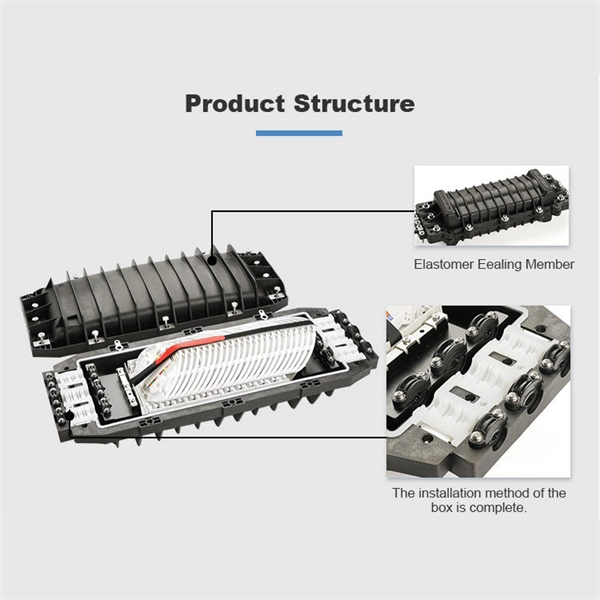
Learn how to install fiber splice trays inside an enclosure step by step. Quick, easy, and essential for fiber pigtail management! https://bit. Unlike fiber connectors, which can be plugged and unplugged, splicing creates a fixed connection that is typically more stable and has lower insertion. This document describes the installation of optical fiber with both single fiber and/or ribbon fiber splices into Optical Splice Enclosure (OSE) metal splice trays (Figure 1). Make sure you read and understand this instruction as well as instructions provided with related assemblies before. By following these detailed steps, the installation of your Fiber Splice Closure will be secure, organized, and maintained, ensuring high performance and longevity of your fiber optic network. Installing a fiber optic splice closure efficiently and effectively requires attention to detail and. How to install the splitter distribution box is the important information we need to know. This article includes the following: 1. Install the fixture 2. Box installation and fixed splitter distribution box 4. Install. Page 5 B (# 7 & 8) enter splice tray # 2. Route the fibers entering the splice tray up to splice point as shown. NOTE : Protection tube from side A enters splice tray from the far end as shown After splicing, close the splice tray and lock the front cover properly with the main and side lock.
[PDF]
For example, in a FTTH network, a single fiber from the telecom provider can serve 32 homes using a 1:32 splitter, eliminating the need for separate fibers to each residence. These unassuming devices enable a single optical signal to be divided into multiple paths, making them indispensable for sharing network resources efficiently—from residential FTTH (Fiber-to-the-Home) connections to large-scale telecom backbones. This guide demystifies fiber optic splitters. You use optical couplers and splitters to split or join signals in fiber networks. These devices help you control light signals well. For example, optical splitters send light to many output ports. It can divide the input optical signal into multiple output optical signals to meet the fiber optic access needs of multiple terminal devices. This type of device plays an important role in passive. A fiber-optic splitter, also known as a beam splitter, is based on a quartz substrate of an integrated waveguide optical power distribution device, similar to a coaxial cable transmission system. The optical network system uses an optical signal coupled to the branch distribution. The fiber optic. If you've ever wondered how a single fiber from your internet service provider can deliver service to an entire neighborhood or apartment building, you've wondered about the magic of optical splitters. The process of light beam splitting involves.
[PDF]
Single-mode optical splitters are optimized for single-mode optical fiber, while multimode optical splitters are tailored for use with multimode optical fiber. An Optical Splitter, also known as a beam splitter, is a passive optical device that divides a single input optical signal into two or more output signals. Conversely, it can also combine multiple signals into one. Its primary role is in Passive Optical Networks (PON), which are the foundation of. This guide demystifies fiber optic splitters, explaining their design, operating principles, types, key specifications, and real-world applications. It can distribute the optical energy transmitted through a single fiber to two or more fibers in a predetermined ratio or combine the optical energy from multiple fibers into one fiber. “Passive” means it needs no. You use optical couplers and splitters to split or join signals in fiber networks. For example, optical splitters send light to many output ports. This lets you connect more users to one network terminal. There are different types of fiber optic splitters available, with two of the most common being Fused Biconical Tapered (FBT) splitters and Planar Lightwave.
[PDF]