An optical time-domain reflectometer (OTDR) is an instrument used to characterize an. It is the optical equivalent of an electronic which measures the of the or under test. An OTDR injects a series of optical pulses into the fiber under test and extracts, from the same end of the fiber, that is scattered () or reflected ba.
[PDF]

An OTDR is a powerful tool that helps technicians and engineers assess the health of fiber optic cables. OTDRs inject high-powered light pulses into the fiber using specialized laser diodes. An optical time-domain reflectometer (OTDR) is an optoelectronic instrument used to characterize an optical fiber. An OTDR injects a series of optical. metry (OTDR), covering its principle, impl e an essential tool for: characterisation, certification, maintenance and monitoring optical networks. Deutsch: Optischer Zeitbereichsreflektometer - Verfahren zur Ermittlung und Analyse von Lauflängen und Reflexionscharakteristika von elektromagnetischen Wellen und Signalen im. Ensure the integrity of your fiber optic network with an Optical Time Domain Reflectometer (OTDR). OTDR testing analyzes fiber optic cable performance from end to end by testing components along the cable, including connection points, bends, and splices. They are mostly used in the technology of optical fiber communications for testing fiber-optic links (e. The OTDR600 is specifically designed for use in factories and laboratories where high linearity and productivity on factory spool lengths are crucial.
[PDF]

Passive receiver that captures an optical signal on a single fiber (1310/1490/1550nm), and demultiplexes it (WDM). The TV signal (1550nm) is converted to an RF output (54-2400MHz), while the 1310/1490nm wavelengths are destined to data signals (GPON) to distribute them through. Facilitates rapid deployment and hassle-free replacement. Contributes to wide coverage and supports multiple optical nodes, facilitating network upgrade and expansion effortlessly. Maintains stable output with minimal gain fluctuation (±0. 5dB) and low noise signature (≤5. Supports. REF. This FTTH WDM Passive Optical Receiver is engineered for high-performance fiber-to-the-home networks. It features a passive design that operates without an external power supply, simplifying installation and reducing maintenance. With integrated WDM technology, it efficiently handles 1310nm/1490nm. Passive FTTH Optical receiver, cost-effective, no need power. ■ High quality plastic case; ■ Digital signal input -10dBm, analog signal input -7dBm; ■ Without power supply and consumption; ■ SC/APC or FC/APC; ■ Output level> 64dBuV (Pin=0dB).
[PDF]
Time domain reflectometers are commonly used for in-place testing of very long cable runs, where it is impractical to dig up or remove what may be a kilometers-long cable. They are indispensable for preventive maintenance of telecommunication lines, as TDRs can detect resistance on joints and connectors as they corrode, and increasing insulation leakage as it degrades and absorbs. OverviewA time-domain reflectometer (TDR) is an electronic instrument used to determine the characteristics of by observing. It can be used to characterize and locate faults in metallic cables (for. A TDR measures reflections along a conductor. In order to measure those reflections, the TDR will transmit an incident signal onto the conductor and listen for its. If the conductor is of a uniform.
[PDF]

For a conventional optical module, we can easily judge the wavelength of the optical module from the color of the latch ring. For example, the black pull ring represents 850nm, and the blue pull ring represents 1310nm. Distinguish the wavelength by the color of the pull ring of the optical module In order to distinguish their own optical modules, different manufacturers can distinguish them by their wavelength, transmission distance, packaging, etc. In the complex infrastructure of data centers, optical modules are critical components that. The utility model discloses a pull ring device suitable for an optical module, and belongs to the technical field of optical communication. This article provides a professional guide on transceiver pull tab color codes by wavelength—spanning SFP, SFP+, CWDM, and BiDi modules—and introduces how LINK-PP standardizes. These modules convert electrical signals into optical signals, which transmit data over distances of fiber optic cables with minimal power loss. The topic of specifications and physical traits is one aspect of this question; another often-overlooked detail is the color of the pull tab. This modest. The ControlLogix® Architecture provides a wide range from high-speed digital to process control. The ControlLogix which allows input information and output status to Rockwell Automation recognizes that some of the terms that are currently used in our industry and in this publication are not in.
[PDF]

Urban Areas: 25–40m spacing (concrete poles, 10–12m height)., steel lattice structures). Factors: Cable weight (kg/km) Ice loading (up to 50mm. The Fiber Optic Association, Inc. (FOA) was founded in 1995 to help develop the workforce to build the fiber optic networks to support a rapid expansion in communications and the Internet. The charter of the FOA was to promote professionalism in fiber optics through education, certification, and. to n utral comm. cable R. FO-CS JOINT USE CLIMBING SPACE REQUIREMENTS 51. APPENDIX A - COVER SHEET / TOC 52. RUS DRAWING #PM12 58. CHECK. d suppliers of electrical construction services. They define a minimum baseline of quality and workmanshi for installing electrical products and systems. NEIS® are intended to be referenced in contrac documents for electrical construction ation or liability to users of this publication. Choose the type of pole The basic pole height is 7m and the tip diameter is 150mm. In case of special sections, crossing obstacles or roads or railways, the pole height of 8m, 9m, etc. can be selected. Cables 300 V or less need to be a minimum two feet over the street light. Climbing Space is an unobstructed, vertical space along the side or corner of the pole. In gen-eral, it consists of an imaginary box, 30-inches square, extending at least 40 inches above the highest communications cable or.
[PDF]
Cost ranges for a residential fiber optic cable run typically span from $1,000 to $12,000, with most projects landing in the $3,000–$8,000 band. The main drivers are trench depth and length, whether the line is buried or aerial, and the in-home termination requirements. The main cost drivers are materials, installation time, and environmental factors that affect trenching, conduit, and terminations. This article provides cost. Installing an optical fiber network is a significant investment that requires careful financial planning. Whether you're upgrading an existing system or starting from scratch, understanding the costs involved can help you allocate your budget wisely. This guide will walk you through the key factors. How Much Does Fiber Optic Cable Cost per Foot? On average, commercial projects range from $5,000 to $20,000 per mile underground and $40,000 to $60,000 per mile for aerial deployment. Individual business connections often cost between $15,000 and $30,000 for 100–200 network drops. Hiring. Homeowners typically pay a broad range for running fiber optic cable from the street to a residence, with the main cost drivers being trenching or aerial installations, cable material, labor time, and permit requirements. The price also varies by fiber type (GPON vs. The price or cost to install fiber reflects material choices, labor hours, and local regulations, with per-mile and per-ft metrics common in.
[PDF]
As an essential component of optical fiber communication, optical modules are optoelectronic devices that facilitate the conversion between optical and electrical signals during the transmission process. Operating at the physical layer of the OSI model, optical modules are core devices in optical. The optical module serves as a crucial component in optical fiber communication systems, operating at the physical layer, which is the lowest layer in the OSI model. Classification of Optical Module: Distinguished according to function, package form, transmission rate, wavelength. In the era of 5G, AI, and high-speed data centers, optical modules serve as the core bridge for converting electrical signals to optical signals (and vice versa), enabling fast, reliable data transmission across networks. They are used in fiber optic communication systems to transmit data over long distances with minimal loss and interference. These modules typically consist of a laser or LED transmitter, a.
[PDF]
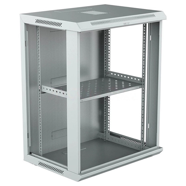
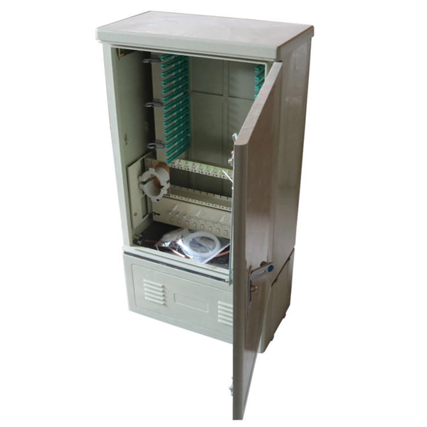
These easy-to-install 20" cable channels can be painted, cut and even turn a 90º angle. Simply attach the uniquely designed wall clips to the wall, secure cables and wires to the fasteners and snap the tunnels onto the clips. Kit includes three long cable . Corning has a wide variety of hardware solutions to choose from to fit your cabling needs. Choose from racks, panels, modules, splice trays, ethernet fiber switches and other structured cabling components. Corning has a variety of hardware solutions including ethernet fiber switches, panels, racks. Often over looked, utilizing tunnel systems to deploy fiber optics, can provide last-mile and intra-city broadband pathways by providing immediate, cost-e ective, and durable deployment routes without disrupting the municipality or mother nature. This fact presents Transit Operators with a unique. Cable Tunnel Kit: The Sanus ELM301 is a cable tunnel kit that conceals and routes even the most complex cable arrangements. This concept significantly optimises the lighting installation. Precision Group's Optical Network Terminals are engineered to safeguard both the ONT and fiber, serving as a secure, all-in-one transition point. Based on customer feedback, our latest optical network terminal designs now include Keystone Ports for router and phone connections, enhancing.
[PDF]

An ideal optical splitter will distribute the light power according to mathematical principle. This is because each of the 8 output ports of the splitter will receive only one-eighth of the. Thorlabs' Single Mode 1x8 Fiber Optic Planar Lightwave Circuit (PLC) Splitters allow a user to split a single input signal evenly into eight output signals, which is ideal for passive optical networks (PON) and other high-channel-count applications. 1×8 splitter means it takes one input fiber and splits the signal into eight outputs. It doesn't need power — it's passive! Great for sharing one signal with many devices, like in FTTH (Fiber To The Home) networks. But light doesn't just split for free. Sharing means each output gets less than the. If we operate with absolute gains measured in relation to 1 milliwatt (mW), they are expressed in dBm, and are calculated as follows: Power Level (dBm) = 10 lg ( mW / 1 ) For “household” needs, in order not to calculate mW to dBm and vice versa every time, here's a ready-made correspondence table:. For instance, a 1:8 splitter ratio signifies an equal distribution of incoming optical power among eight output ports, with each port receiving 1/8th of the total power. It has one input port and eight output ports, making it ideal for applications where a signal needs to be.
[PDF]

The receiver of an optical module has an overload point. Therefore, an optical attenuator is required to reduce the optical power. By introducing a precise and constant amount of optical loss, it ensures that the incoming signal remains within the optimal operating range of the receiver. A. Average optical power refers to the optical power outputted by the optical module's transmitter under normal working conditions, which can be understood as the intensity of light. The transmitted optical power is related to the proportion of "1"s in the transmitted data signal; the more "1"s, the. The receiver of an optical module has an overload point. If the optical power received by the receiver is excessively high, the optical module will be burnt. In addition, during signal transmission in a WDM system, the. 📦 For purchasing, use the RP Photonics Buyer's Guide for optical attenuators. It provides an expert-curated supplier directory, buyer-focused technical background information, and structured selection criteria to support professional procurement decisions. Optical attenuators are devices that. An optical attenuator, or fiber optic attenuator, is a device used to reduce the power level of an optical signal, either in free space or in an optical fiber. Optical internetworks are data networks composed of routers and data.
[PDF]
An optical module is a typically hot-pluggable optical transceiver used in high-bandwidth data communications applications. Optical modules typically have an electrical interface on the side that connects to the inside of the system and an optical interface on the side that connects to the outside world through a fiber optic cable. The form factor and electrical interface are often specified by an int. Electrical Interface TypesThere have been multiple variants of the electrical interface of optical modules that have been used over the years. The earliest forms of optical modules had an analog electrical interface. In the transmit dir. Many different forms of optical modulation and multiplexing have been employed in optical modules. The most common modulation technique historically has been or NRZ.
[PDF]
BiDi SFP+ changes the geometry: each module uses a single fiber pair directionally separated by wavelength, so you can run one strand where you previously needed two. One of the most common decisions network engineers face is selecting between single fiber SFP and dual fiber SFP modules. This comprehensive guide explores the differences between single and dual fiber SFPs, their respective benefits, limitations, and use cases—helping you make an informed choice. A single fiber SFP, also known as a BiDi SFP, is designed precisely for this purpose—enabling bidirectional data transmission over a single strand of optical fiber. Unlike traditional SFP transceivers that require two fibers—one for transmitting and one for receiving—a single fiber SFP uses. SFP (Small Form-factor Pluggable) is a compact, hot-pluggable network interface module used to connect network devices (switches, routers, firewalls) to fiber optic or copper cables. An SFP interface on networking hardware is a modular slot for a media-specific transceiver, such as for a fiber-optic cable or a copper. Both transmitting and receiving need one optical fiber to connect. Simplex SFP modules, also known as BIDI transceiver, employs a unidirectional transmission mechanism and have only one port. In practice, that means fewer splice points, smaller patch panels, and less conduit congestion—especially in retrofit buildings.
[PDF]