Digital Diagnostic Monitoring (DDM) can monitor parameters of the optical module regularly and generate alarms when parameter values exceed thresholds. By using DDM, you can detect issues early to maintain network stability. When you configure the DDM function, follow these notes. Optical Module Monitoring & Troubleshooting 2026 – network-switch. com Digital Diagnostics Monitoring (DDM), also known as Digital Optical Monitoring (DOM) or Diagnostic Monitoring Interface (DMI), is a standardized feature defined by SFF-8472 that allows network devices to monitor real-time optical. Digital Diagnostic Monitoring (DDM), also known as Digital Optical Monitoring (DOM), is a key feature in modern optical transceivers. It can provide the host with real-time data about the module's internal operating conditions, including parameters such as voltage. Digital Diagnostics Monitoring (DDM) is a feature used in optical transceiver modules that enables you to view real-time information about transceivers, such as optical output and input power. For information about which F5 ® transceiver modules support DDM, see F5® Platforms: Accessories. It is an intelligent function that enables network administrators to monitor the transceiver's operational parameters in real time. DDM is not merely a feature; it is an industrialized standard.
[PDF]
An optical module is a typically hot-pluggable optical transceiver used in high-bandwidth data communications applications. Optical modules typically have an electrical interface on the side that connects to the inside of the system and an optical interface on the side that connects to the outside world through a fiber optic cable. The form factor and electrical interface are often specified by an int. Electrical Interface TypesThere have been multiple variants of the electrical interface of optical modules that have been used over the years. The earliest forms of optical modules had an analog electrical interface. In the transmit dir. Many different forms of optical modulation and multiplexing have been employed in optical modules. The most common modulation technique historically has been or NRZ.
[PDF]

Explore a comprehensive guide to residential electric meter box wiring diagrams, offering clear instructions for safe and efficient installation. A distribution box is the heart of any electrical system. It takes the incoming power and safely distributes it to different circuits throughout your building. However, the key to. Learn how to wire a distribution box step by step! This video shows real on-site footage of electrical installation, demonstrating safe and standardized wiring methods used by professionals. It has three categories: residential, commercial and industrial electrical distribution boxes, all of which play important roles in their respective electrical. Cleaning of the various PXBCM device housings should only be done with power and mains disconnected. A clean dry rag can be used to remove dust. No liquids should be used. Catalog Numbers Catalog Number DescriptionSuffix De- scription Notes PXBCM-MB Meter Base PXBCM-MMS-L09-A Meter Module Strip. full turn-key system solution backed with industry leading reliability and performance. Applications - The minimally invasive retrofit kit enables the opportunity existing remote power infrastructure cross arm, & wiring) providing the total cost of ownership. Failure to strictly adhere to the.
[PDF]

The PL-1000D simultaneously monitors up to 16 fiber strands, eight on the OTDR and eight on the OSA, and operates standalone over dark fiber, lighted fiber, or a third party network without impacting network traffic. The device monitors the entire D. The PL-1000D simultaneously monitors up to 16 fiber strands, eight on the OTDR and eight on the OSA, and operates standalone over dark fiber, lighted fiber, or a third party network without impacting network traffic. The device monitors the entire DWDM C-band spectrum and provides the optical spectrum, OSNR, and OTDR measurements of the fiber. The OTDR locates fiber cut by sending high powered optical pulses into the fiber and creating Rayleigh back-reflections. The returning signals are measured and calculated, indicating the accurate location and intensity of the fault. The OTDR supports GIS (Geographic Information System) using Rest API, enabling precise geographic location of disrupt. The OSA enables the user to monitor the OSNR and optical spectrum of each fiber and shows a full, accurate and detailed picture of the wavelengths used in the fiber. OSADiagram Graphical Display of the OSA, from PacketLight's LightWatch NMS Please contact usfor a quote or further assistance.
[PDF]
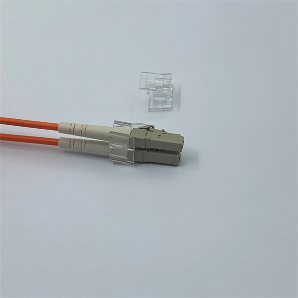
The FC/PC (Physical Contact) and FC/APC (Angled Physical Contact) fiber optic connectors are standardized under TIA EIA/TIA-604-4 and IEC 61754-13. ABSTRACT: This standard describes the point-to-point physical interface portions of Fibre Channel serial electrical and optical link variants that support the higher level Fibre Channel protocols includ-ing FC-FS, HIPPI, IPI, SCSI and others. This standard is recommended for new implementations but. Fiber connector types LC, SC, FC, ST, MTP, and MPO are widely used in past and present. What are the differences between them? Who is the most popular one? Find the answer in the article. What is a Fiber Connector? The optical fiber connector is a kind of detachable passive optical component used. An optical fiber connector is a device used to link optical fibers, facilitating the efficient transmission of light signals. An optical fiber connector enables quicker connection and disconnection than splicing. Unlike fiber splicing, which is permanent, connectors allow for easy connection and disconnection of cables, making them ideal for maintenance and flexibility in. Understanding fiber connector types—SC/APC, SC/PC, LC/UPC, LC/APC, ST/PC, FC/PC, and FC/APC—is essential for selecting the right interface for your application. Each type varies by shape, polish (APC, PC, or UPC), and return loss performance, which affect PC, UPC, and APC Polish Styles: What's the.
[PDF]

Of the more than a dozen types of fibre-optic connectors available, the four most commonly used today are LC, SC, FC, and ST. Fiber connector types LC, SC, FC, ST, MTP, and MPO are widely used in past and present. What are the differences between them? Who is the most popular one? Find the answer in the article. What is a Fiber Connector? The optical fiber connector is a kind of detachable passive optical component used. Fiber optic connectors are the unsung heroes of modern networking. They are small, often overlooked components, yet they are essential for ensuring high-speed, low-loss, and reliable optical transmission. In addition to serving the same general function, the four connectors differ in size, locking mechanism, and best applications. The following guide systematically describes. Choosing the right connector for an optical link is one of those small decisions that has outsized effects on installation density, reliability, and long-term maintenance. broadband connection is available everywhere. Its. Optical fiber terminations are the mechanical and optical interfaces that connect fiber cables to equipment, patch panels, and network hardware. They directly affect insertion loss, return loss, reliability, and long-term network stability. In this guide, we break down the most common optical fiber.
[PDF]

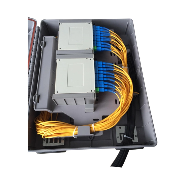
The Patch and Splice Combo Patch Panel is designed to allow both the patching and splicing of fiber optic cable all in one unit; these particular units have fiber termination panels in the upper slide out shelf and splice trays in the lower shelf. NG4access ® Cabled Modules available in all module sizes and fiber counts up to 864 fibers NG4access ® Splice Tray Four sizes of interchangeable Propel fiber pass-through adapter packs provide the breadth of capabilities for virtually any configuration. Four sizes of interchangeable Propel fiber. Cisco is introducing a family of fiber management solutions with a debut of SMF and MMF patch panels. The panels will enable Cisco's customers to facilitate breakout connectivity agnostic of the data rate. The Cisco® solution of panel and cable assemblies offers versatile solution for any breakout. Our fiber patch panel offers options for flexible cable management and seamless integration with various cassettes and fiber optic accessories. Allowing full front access for network. Foss FP-series front patch panels are made with the highest accuracy for precise fitting. All panels are tested according to both our own quality measures and international standards before they are sent to customers. Similarly, the ABS High Density Shelves bring a new level of access, convenience, and security to its Fiber Splice Shelf, enabling quick and easy fiber splicing and connectivity for rack mount applications.
[PDF]
The term host bus adapter (HBA) may be used to refer to a interface card. In this case, it allows devices in a Fibre Channel to communicate data between each other – it may connect a server to a switch or storage device, connect multiple storage systems, or connect multiple servers. Fibre Channel HBAs are available for, computer architectures, and buses, i.
[PDF]

The interface fc command displays the Fibre Channel (FC) interface view. Specifies the number of an FC interface. Devices on a storage area network (SAN) use FC interfaces to communicate and carry traffic. You can then perform. FC switches are required for applying for DESS devices of the common I/O (low latency), high I/O (low latency), or ultra-high I/O (low latency) types. An FC switch is a high-speed network transfer device that uses optical fibers as the media. It features high-speed transfer and strong. Get the latest official Huawei FC - Application Interface port (COM/LPT/Serial) drivers for Windows 11, 10, 8. Update drivers using the largest database. The good news is that HF now shows two ports in the COM dropdown and is recognized in Mobile Partner! The bad news is that reading still fails, no matter what port combo I specify, even modem port. These are the observations before/after setting AT^SFM=1. Thus we lost SD card as a recognized drive. Copyright © 1998-2026 Huawei Device Co. FCF functions as the access switch and connects the storage device Array through its uplink interfaces, and directly connects to ServerA through its downlink interface, as shown in Figure 2-35. ServerA connects to FCFA and FCFB to constitute dual-plane networking, ensuring network reliability.
[PDF]
FC used throughout all applications for Fibre Channel infrastructure and devices, including edge and ISL interconnects. Each speed maintains backward compatibility at least two previous generations (I.e., 32GFC backward compatible to 16GFC and 8GFC)OverviewFibre Channel (FC) is a high-speed data transfer protocol providing in-order, lossless delivery of raw block data. Fibre Channel is primarily used to connect to in (SAN) in co. When the technology was originally devised, it ran over optical fiber cables only and, as such, was called "Fiber Channel". Later, the ability to run over copper cabling was added to the specification. In order to avoid confu.
[PDF]
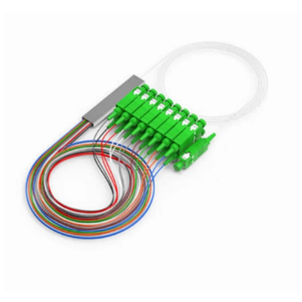
Based on analysis on the dispersion of the optical system of a MEMS-based VOA, we provide a method to reduce the WDL significantly with minor revision on the end-face angle of the collimating lens. 📦 For purchasing, use the RP Photonics Buyer's Guide for variable optical attenuators. It provides an expert-curated supplier directory, buyer-focused technical background information, and structured selection criteria to support professional procurement decisions. Variable optical attenuators are. An optical attenuator, or fiber optic attenuator, is a device used to reduce the power level of an optical signal, either in free space or in an optical fiber. The basic types of optical attenuators are fixed, step-wise variable, and continuously variable. Optical attenuators are commonly used in. Applications in broadband optical fiber communication system need variable optical attenuators (VOAs) with low wavelength-dependent loss (WDL). What Are Fiber Optic Attenuators? Fiber optic attenuators, also called optical attenuators, are passive. Optical attenuators are categorized based on their attenuation mechanism and adjustability: Fixed Optical Attenuators: These attenuators reduce the signal power by a predetermined value and are used in applications where a constant level of attenuation is required. It works by dissipating a portion of the optical power passing through it, thereby lowering the overall power level. Fiber optic attenuators.
[PDF]