No, a 10G SFP (Small Form-factor Pluggable) module is designed to operate at 10 Gigabits per second (Gbps) and is not compatible with a 1 Gigabit per second (Gb) port. Therefore, a 10G SFP module will not work. When SFP optical module is inserted into the SFP port of Gigabit switch with fiber optic patch cable or copper cable, it can realize different distance transmission. For example, the maximum transmission distance is 160 km when using SFP1G-ZXC-55 optical module and LC duplex fiber patch cable, and. 10 Gigabit Ethernet (10GE, 10GbE, or 10 GigE) is a group of computer networking technologies for transmitting Ethernet frames at a rate of 10 gigabits per second. It was first defined by the IEEE 802. For example, when using the AE-SFP-ZX160 optical module and LC duplex fiber optic patch cords, the maximum transmission. Can 1G SFP optics work with 10Gb SFP+ ports on a 10Gb switch, or vice versa? This comprehensive guide reveals the intricacies of SFP and SFP+ compatibility and provides useful solutions for network switch users. Can 1G SFP Optics Run at 10G SFP+ Port? Can 10G SFP+ Optics Run at 1G SFP Port? Can. Small form-factor pluggable or SFP Modules can be described as compact and hot-pluggable hardware that connects various networking devices such as servers, routers, and switches. Networking standards, including Ethernet, Fiber Channel, and SONET, are also used with the SFP modules, broadening their.
[PDF]
The transceiver is available as a mini-GBIC form factor, making it ideal for environments that require many fiber connections by taking up less space in your cabinet and/or computer room. Compatibility in your network is everything, and the Intellinet SFP Transceiver Module delivers. Use it with any Intellinet SFP equipped network switch or any other MSA-compliant, SFP-enabled switch. And since the Intellinet SFP transceiver module is set to broadcast the vendor on GLC-LH-SM, compatibility to your Cisco gear is provided. No need to power down your LAN switch in order to install or remove the transceiver. This makes it very convenient and easy for you to make adjustments to your network that allow your business to keep pace with the changing demands of the market.
[PDF]

The SS64S16A (L-16. 2,SC) is a Huawei high-performance STM-16 optical interface board designed to deliver 2. 5 Gbps long-haul transmission across SDH transport networks. The SFP-FE-SX-MM1310 (part number: 02315233) is a Huawei-certified 100M optical module. However, the Vendor Name field displays the original manufacturer name, instead of HUAWEI. Huawei. Optical modules are widely used in switches, network interface cards (NICs), routers, and other communication devices. During use, reading optical module information helps understand its real-time operating status, enabling faster troubleshooting of link abnormalities. The following uses the. Original SFP Huawei GPON-OLT-CLASS-C+/C++ Optical Module GPON Optical Module A GPON optical module is connected to one SC optical fiber to provide GPON access service. Return Material Authorization (RMA) Process Standard Hardware Warranty Policy: Original new sealed ZTE product: 1 Year The Support. Problem: All optical ports cannot be connected, and the indicator lights are not on. Solution: To solve this problem, you can follow these steps: Check if the fiber and optical modules are compatible. Perform a. Huawei GPON boards include GPON, XG-PON, XGS-PON, XG-PON&GPON Combo, XGS-PON&GPON Combo interface board, so there are these kinds of GPON optical modules corresponding. The following figure shows the optical modules supported by the S5720-12TP-LI-AC. You can also use the Hardware Center to query the.
[PDF]

How to Install a Fibre Connector into a Patch Panel (Easy fibre optic connector installation) How to Install a Fibre Connector into a Fibre Optic Patch Panel. How do you install fibre optic connectors?. Connecting a fiber patch panel to a switch is a critical step in setting up a fiber optic network. There are different types of connectors. In today's high-performance networks, fiber optic patch cables are the lifelines that ensure smooth data flow across switches, servers, and routers. Even the most advanced optical transceivers can only perform at their peak when paired with properly installed, clean, and precisely managed fiber. Choose an SFP module based on the fiber optic cabling that will be connected to the network switches. SFP transceiver modules almost always require two fiber optic cable strands. A Fiber Patch cord connects two devices. You plug it into a switch, router, or patch panel. It's ready to use out of the box. A pigtail is for splicing. You fuse it to a. With a railroad switch (patch panel), the train (data) can travel from A to B, C and even more destinations, otherwise it can only go from A to B, or C to D. This article, What Is a Patch Panel Used for?, has explained it thoroughly.
[PDF]
GYTA is an outdoor stranded loose tube fiber optic cable with aluminum tape armor (indicated by the “A” in GYTA). It is designed for aerial and duct installations but is not recommended for direct burial. It provides an excellent balance of moisture protection and mechanical flexibility, making it the preferred choice for duct and aerial backbone networks. Perfect for long-distance communication. We manufacture high quality products according to European and US standards. The aluminum. Outdoor Duct Optical Cables are strands of specially designed fiber optic cable that are ideally suitable for deployment in underground conduits or ducts. This type of cable guarantees total security for optical fibers while providing long-distance, high-speed data transmission. We supply GYTA fiber optic cable from 2 fiber cores to 288 fiber cores. Both single mode type and multimode types are available. precise control for fiber excess. GYTA fiber optic cable is an outdoor loose tube cable that uses aluminum tape armor for additional mechanical protection. This cable design is commonly installed inside underground ducts or conduits where fiber cables require protection from external pressure and environmental conditions. It is known for its high tensile strength, high flexibility, and excellent transmission performance. In this article, we will discuss the characteristics of the GYTA optical cable.
[PDF]
Optical cable junction boxes play a crucial role in connecting and protecting optical fibers, directly influencing the quality and lifespan of optical cable routes. Optical cable splice boxes protect the splicing parts of optical fibers from various hazards, such as water seepage due to adverse. Optical cable junction boxes play a crucial role in managing and organizing fiber optic networks. It serves as a termination point for fiber optic cables, providing protection and distribution of the optical fibers while ensuring efficient signal transmission. Utilizing an optical junction box can significantly enhance your. Optical cable splice box is a popular name, its scientific name is optical cable splicing box, also known as optical cable splicing package, optical cable splicing package and gun barrel. These boxes are designed to house and protect fiber optic splices and terminations, ensuring that the delicate fibers are safeguarded from.
[PDF]
An optical module is a typically hot-pluggable optical transceiver used in high-bandwidth data communications applications. Optical modules typically have an electrical interface on the side that connects to the inside of the system and an optical interface on the side that connects to the outside world through a fiber optic cable. The form factor and electrical interface are often specified by an int. Electrical Interface TypesThere have been multiple variants of the electrical interface of optical modules that have been used over the years. The earliest forms of optical modules had an analog electrical interface. In the transmit dir. Many different forms of optical modulation and multiplexing have been employed in optical modules. The most common modulation technique historically has been or NRZ.
[PDF]
The answer is yes, and it's a practice widely used in the industry to distribute signals to multiple destinations without degrading the signal quality significantly. This article delves into the methods, benefits, challenges, and practical applications of splitting fiber lines. In principle, an optical cable can be split, but it's not as simple as just cutting the cable and attaching multiple devices. There are two primary methods of splitting an optical cable: Passive splitting involves using a specialized device called an optical splitter. This device takes the incoming. A fiber optic splitter is a passive optical component that divides a single incoming optical signal into two or more outgoing signals, or combines multiple incoming signals into one. What is Fiber Line. An optical splitter, also known as a beam splitter, fiber splitter, or fiber optic splitter, serves as a vital passive component in optical communication systems. Its primary function is to split the optical signal of one input optical fiber into multiple optical signals and transmit them to. An MPO breakout cable is a fiber optic cable designed to split a single multi-fiber connection into multiple separate connections. Fiber optic splitters have applications such as Fiber to the Home (FTTH) and Passive.
[PDF]
Fiber optic cables are, like their name suggests, a cable that uses light, rather than electricity to transmit information. They're made from silica glass fibers about the same width as a human hair, which all.
[PDF]
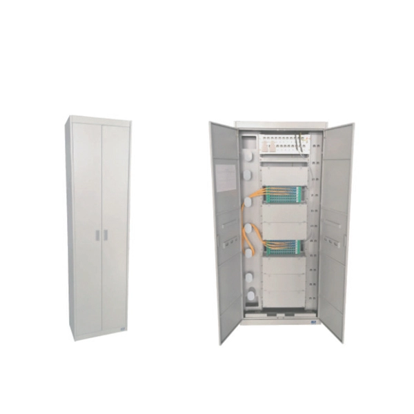
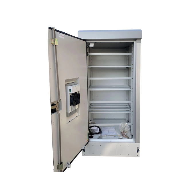
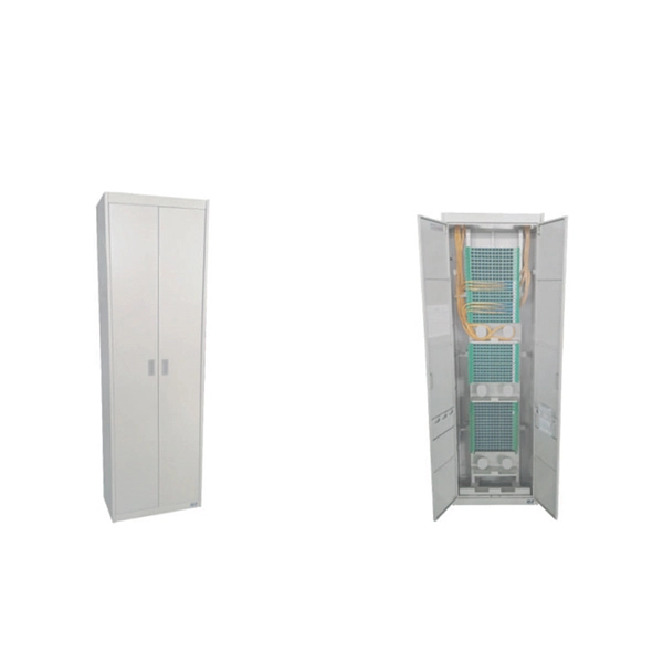
A distribution box, also known as a fiber distribution hub or optical distribution box, is a larger enclosure designed to manage and distribute fiber optic cables to multiple endpoints. It serves as a central point for connecting and organizing numerous fiber optic. Although all three are related to fiber connection and management, their installation locations, functional roles, and positions within the network architecture are fundamentally different. Confusing these devices may lead to non-standard cabling at best, and serious challenges in network. In modern FTTH (Fiber to the Home) and optical communication networks, three types of fiber distribution products are widely used: Splitter Distribution Box, ODF (Optical Distribution Frame), and Fiber Terminal Box. The functions of the four connectors can be. First, let us learn the common point among ODF, fibre optic termination box and fiber optical distribution box, actually, they have similar function, we sort out them as following 4 aspects: 1. fiber termination and optical signal splitting 4. What is the difference between these fiber boxes.
[PDF]
A photonic integrated circuit (PIC) or integrated optical circuit is a microchip containing two or more photonic components that form a functioning circuit. This technology detects, generates, transports, and processes light. Photonic integrated circuits use photons (or particles of light) as. architecture and performance of several generations of InP-based PICs. Increased complexity in chip functionality has resulted in a need for increased fabricati n complexity from III-V epitaxy, through wafer fab, die fab, and test. Through continuous learning and improvement, Infinera has. Photonic integrated circuits (PICs) use light (photons) to transmit information, whereas traditional integrated circuits use electricity (electrons), enabling faster signal propagation. Whereas an electronic integrated circuit.
[PDF]

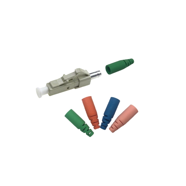
Fiber optic terminal boxes provide functions such as input, branching and splicing of optical fiber cables. Through the connectors and splicing boxes in the terminal box, optical fibers can be quickly connected and repaired. Serving as a critical connection point, FTB facilitates the termination, splicing, or connection of fibers from various cables to other network devices such as switches, routers, or Optical Network Terminals (ONTs). It aids in splicing, splitting, storing, and managing fibers within the appropriate. The optical fiber terminal box is the terminal joint of an optical cable, one end of which is an optical cable, and the other end is a pigtail, which is equivalent to a device that splits an optical cable into a single optical fiber. A fiber pigtail is a specific hardware connection used for cable termination. It is a small enclosure that can house and protect the fiber optic cables, splices, and connectors. The optical fiber termination box and optical fiber splice box serve distinct purposes and are not interchangeable.
[PDF]

This paper is focused on the performance analysis of protection mechanisms utilized in common wavelength division multiplexing-based passive optical networks. Wavelength division multiplexers are fundamental to the functioning and performance of integrated photonic circuits, with applications ranging from optical interconnects to sensing and quantum technologies. Current solutions are limited by trade-offs between channel spacing, crosstalk, insertion. Wavelength division multiplexing (WDM) is a technology for increasing the transmission capacity of optical fiber communications by sending multiple data channels simultaneously through a single fiber, each on a different wavelength of light. The main aim of the proposed research is providing an option of comparing different traffic protection scenarios for advanced optical. Herein, an attention-grabbing and up-to-date review related to major multiplexing techniques is presented which includes wavelength division multiplexing (WDM), polarization division multiplexing (PDM), space division multiplexing (SDM), mode division multiplexing (MDM) and orbital angular momentum. The journey of optical multiplexing began in the 1970s with the introduction of Wavelength Division Multiplexing (WDM), which revolutionized the capacity of optical communication systems. The primary objective of optical multiplexing has been to maximize the utilization of available bandwidth in.
[PDF]