The STAR Module enables thermal and structural deformation data from FEA packages to be imported directly into OpticStudio where the impact on the performance of your optical system can be analysed. Articles in this section provide guidance on using the Ansys Zemax OpticStudio Enterprise-only feature: STAR. STAR tools allow you to integrate deformation, thermal, and stress effects into your optical design. When you use STAR to import structural FEA data onto a diffractive surface. When constructing fiber-optic transmission lines, the optical cable during the installation and installation process is inevitably subject to external mechanical influences. After completion of construction, especially in regions with significant seasonal temperature fluctuations, residual. Thermo-optical simulation is an important extension of classical ray-tracing because many applications, especially in laser technology, have to deal with thermal effects. This enables a deep understanding of the behaviour of your system. Optical beam deflection is a popular method to measure the deformation of micromechanical devices. We present a method to evaluate precisely these parameters, using the relative amplitude of.
[PDF]
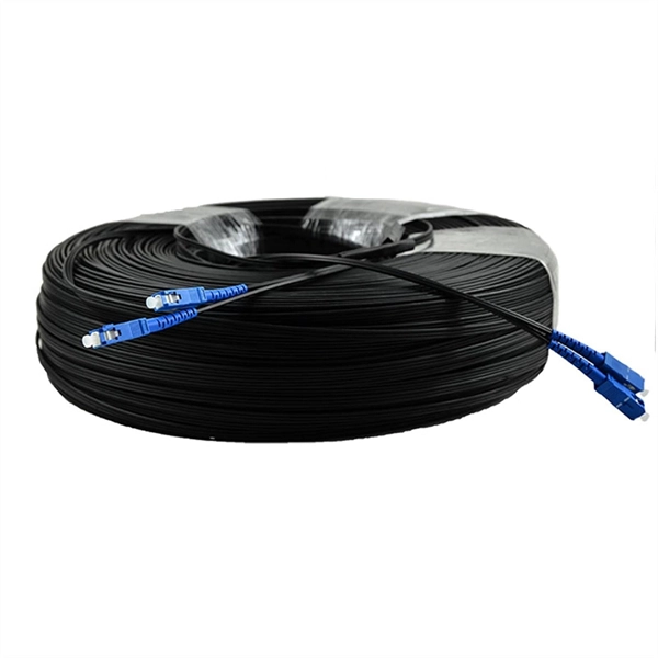
GYTA is an outdoor stranded loose tube fiber optic cable with aluminum tape armor (indicated by the “A” in GYTA). It is designed for aerial and duct installations but is not recommended for direct burial. It provides an excellent balance of moisture protection and mechanical flexibility, making it the preferred choice for duct and aerial backbone networks. Perfect for long-distance communication. We manufacture high quality products according to European and US standards. The aluminum. Outdoor Duct Optical Cables are strands of specially designed fiber optic cable that are ideally suitable for deployment in underground conduits or ducts. This type of cable guarantees total security for optical fibers while providing long-distance, high-speed data transmission. We supply GYTA fiber optic cable from 2 fiber cores to 288 fiber cores. Both single mode type and multimode types are available. precise control for fiber excess. GYTA fiber optic cable is an outdoor loose tube cable that uses aluminum tape armor for additional mechanical protection. This cable design is commonly installed inside underground ducts or conduits where fiber cables require protection from external pressure and environmental conditions. It is known for its high tensile strength, high flexibility, and excellent transmission performance. In this article, we will discuss the characteristics of the GYTA optical cable.
[PDF]
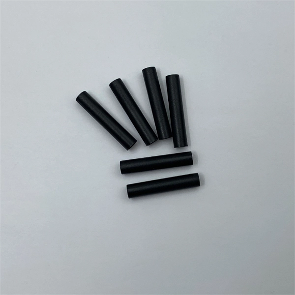
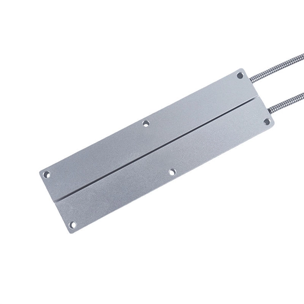
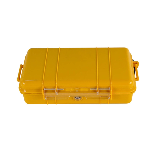
Optical cable junction boxes play a crucial role in connecting and protecting optical fibers, directly influencing the quality and lifespan of optical cable routes. Optical cable splice boxes protect the splicing parts of optical fibers from various hazards, such as water seepage due to adverse. Optical cable junction boxes play a crucial role in managing and organizing fiber optic networks. It serves as a termination point for fiber optic cables, providing protection and distribution of the optical fibers while ensuring efficient signal transmission. Utilizing an optical junction box can significantly enhance your. Optical cable splice box is a popular name, its scientific name is optical cable splicing box, also known as optical cable splicing package, optical cable splicing package and gun barrel. These boxes are designed to house and protect fiber optic splices and terminations, ensuring that the delicate fibers are safeguarded from.
[PDF]
The answer is yes, and it's a practice widely used in the industry to distribute signals to multiple destinations without degrading the signal quality significantly. This article delves into the methods, benefits, challenges, and practical applications of splitting fiber lines. In principle, an optical cable can be split, but it's not as simple as just cutting the cable and attaching multiple devices. There are two primary methods of splitting an optical cable: Passive splitting involves using a specialized device called an optical splitter. This device takes the incoming. A fiber optic splitter is a passive optical component that divides a single incoming optical signal into two or more outgoing signals, or combines multiple incoming signals into one. What is Fiber Line. An optical splitter, also known as a beam splitter, fiber splitter, or fiber optic splitter, serves as a vital passive component in optical communication systems. Its primary function is to split the optical signal of one input optical fiber into multiple optical signals and transmit them to. An MPO breakout cable is a fiber optic cable designed to split a single multi-fiber connection into multiple separate connections. Fiber optic splitters have applications such as Fiber to the Home (FTTH) and Passive.
[PDF]
BiDi SFP+ changes the geometry: each module uses a single fiber pair directionally separated by wavelength, so you can run one strand where you previously needed two. One of the most common decisions network engineers face is selecting between single fiber SFP and dual fiber SFP modules. This comprehensive guide explores the differences between single and dual fiber SFPs, their respective benefits, limitations, and use cases—helping you make an informed choice. A single fiber SFP, also known as a BiDi SFP, is designed precisely for this purpose—enabling bidirectional data transmission over a single strand of optical fiber. Unlike traditional SFP transceivers that require two fibers—one for transmitting and one for receiving—a single fiber SFP uses. SFP (Small Form-factor Pluggable) is a compact, hot-pluggable network interface module used to connect network devices (switches, routers, firewalls) to fiber optic or copper cables. An SFP interface on networking hardware is a modular slot for a media-specific transceiver, such as for a fiber-optic cable or a copper. Both transmitting and receiving need one optical fiber to connect. Simplex SFP modules, also known as BIDI transceiver, employs a unidirectional transmission mechanism and have only one port. In practice, that means fewer splice points, smaller patch panels, and less conduit congestion—especially in retrofit buildings.
[PDF]

On average, you can rent a Fusion Splicer for $275/day, $773/week, $1424/month. The price of these splicers can be higher because of their mechanical complexity and ability to handle various fiber types, including large-core fibers. Hybrid splicers bring in various features that are present in both automatic splicers and manual splicers. They can be aligned by the core. Fiber optic fusion splicers are critical tools for deploying and maintaining fiber networks, with significant variations in performance, features, and pricing. This guide breaks down the key cost-influencing factors across five dimensions—splicer types, technology, performance, accessories, and. A fiber optic splicing machine is a specialized machine used to fuse two optical fibers together to form one long one. The machine, also known as a fiber optic fusion splicer, uses electricity to melt the two optic cables into one. The fiber fusion splicer conducts the fusion with high accuracy to. Check each product page for other buying options. Get reliable equipment with fast splicing times and comprehensive accessories included. It features a mini handheld design, integrated buttons and touch screen, simple operation, low.
[PDF]
The Open Systems Interconnection (OSI) model is a developed by the (ISO) that "provides a common basis for the coordination of standards development for the purpose of systems interconnection." In the OSI reference model, the components of a communication system are disting.
[PDF]
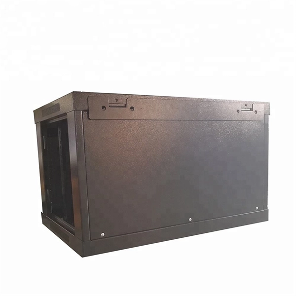
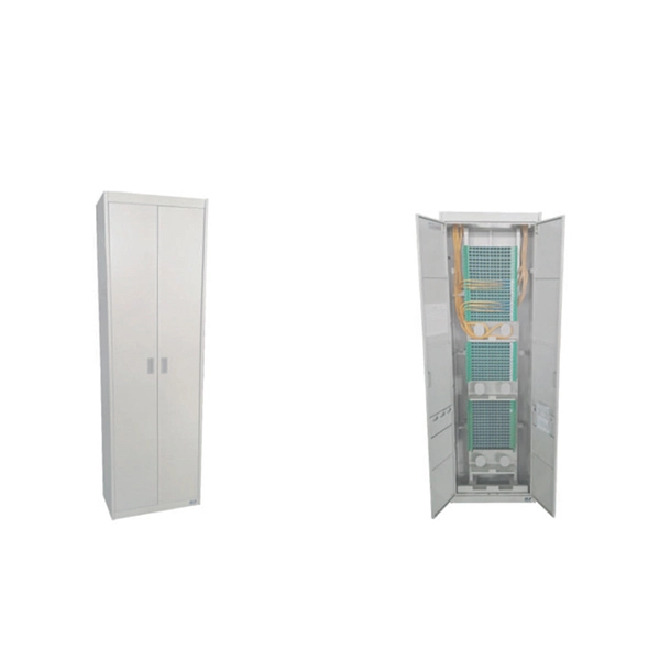
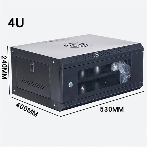
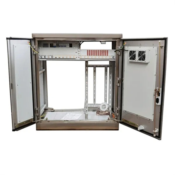
The information contained in this manual should serve as a guide to proper handling, installing, testing, and for troubleshooting problems with fiber optic cables. Optical fibers require special care during installation to ensure reliable operation. FIBER OPTIC CROSS CONNECTION CABINET 144, 288 AND 576 FIBER. Open the cabinet base cover, fix the cabinet on the Cement base. (Fig 1) PLEASE READ THESE INSTRUCTIONS CAREFULLY. Keeping this page as a placeholder for now. Have any questions? Talk with us directly using LiveChat. 0 SCOPE Fiber optic cross connect cabinet is an outdoor optical equipment that is especially designed for outdoor optical nodes in access network. WTC144 ACCOMMODATES ALL CROSS CONNECT FUNCTIONS (SPLICING, TERMINATION, AND INTERCONNECTION) FOR OUTSIDE PLANT, BACKBONE, AND BUILDING CABLES. WTC144 CABINETS CAN BE ORDERED EMPTY, LOADED, OR CUSTOM CONFIGURED TO YOUR PARTICULAR SPECIFICATIONS.
[PDF]
Cable TypePrice Range (USD/meter)Simplex / Duplex Indoor Cable$0. 30Single-mode Outdoor Cable$0. 50Multimode (OM1/OM2/OM3)$0. 60Armored Cable (Steel Tape / FRP)$0. 50 These are indicative prices. Buyers typically pay for fiber optic cable by length, fiber type, and installation complexity. Main cost drivers include cable grade (indoor vs outdoor, armoured), distance, and labor for trenching, splicing, and termination. Data aggregated from Q1 2026 contractor invoices across Texas, Ohio, and North Carolina. Cost per foot of fiber. How Much Does Fiber Optic Installation Cost Per Foot? Cable Material Costs: Installation Costs by Method: Prices can range from $1 to $50+ per linear foot depending on the method and complexity. The initial cost of installing fiber optic cables can vary depending on the chosen installation method. Cable installation price refers to the total cost of deploying fibre or copper cabling across a site. It includes labour, materials, termination methods, routing complexity, and any environmental factors such as trenching or conduit work. When you plan a structured cabling project, the cost of. Because the core is wider and harder to manufacture to 2025 standards, it's a jump in price: $1. Armored cables: If there's any chance of a shovel or a rat hitting that line, you need steel tape armor. That “insurance” That 'insurance' bumps the price to $1. 50 per meter, depending on several variables.
[PDF]
The SFP-1040-WB is a BiDirectional single fiber strand 10G SFP+ optical module using Tx:1330nm and Rx:1270nm wavelengths. The transceiver supports all 10G rated speeds for Ethernet, SONET, SDH or Fibre Channel networks. SFP-1040-WB must be paired with the SFP-1040-WA model to have an operational. The SFP-1040-Wx series single mode transceiver is small form factor pluggable module for duplex optical data communications such as 10GBASE-ER/EW defined by IEEE 802. It has the SFP+ 20-pin connector to allow hot plug capability. All modules satisfy class I laser safety requirements. Digital diagnostics functions are available via a 2-wire serial. The SFP-1040-Dxx is a DWDM 10G SFP+ optical module. It is available for all 45 DWDM 100GHz ITU grid wavelength channels. The transmitter section uses a 1550nm EML, which is class 1 laser compli Rate Select 0, optionally controls SFP+ module recei e Select 1, optionally controls SFP+ module.
[PDF]
from outside the US. EMEA Specific: +49 (0) 228 7489 201 HCS and GiHCS are registered tradema time without notice. This document is for informational purposes only and is not intended to modify or supplement any OFS warranties or specifications relating to any of its. from outside the US. STFOC uses our patented cable jacket construction designed to protect the fiber in the harsh subsea environment. Non-KinkTMSTFOC has a patented design to protect. CommScope bundles hybrid cabling to your custom specifications, using our high-performance fiber-optic, unshielded twisted pair and coaxial cables. Devices deployed at the network edge—a 5G radio, a security camera, or an industrial sensor—require high-speed data connectivity and power. It is technically possible to have a separate fiber and electrical cable, but it adds complexity, cost, and maintenance overhead. Optical hybrid cables address. challenge—OCC has what you need. Our team will make sure the configuration is tailored to your needs and will provide a detailed quote. Email us using the Request a Quote below, or give our team a call. Drive, Avon, CT 0600 erat ing Bend Radiu erat ing Bend Radius Cons from outside the US. Teledyne ODI ofers a comprehensive line of fiber optic and electro/optic hybrid wet mate interconnect products. Wet mate connectors are available in ROV Mate, Stab Mate and Manual Mate configurati sm.
[PDF]
Find low everyday prices and buy online for delivery or in-store pick-up. Find low everyday prices and buy online for delivery or in-store pick-up. Shop products from small business brands sold in Amazon's store. Discover more about the small businesses partnering with Amazon and Amazon's commitment to empowering them. Learn more Made with chemicals safer for human health and the environment. Manufactured on farms or in facilities that protect. 20pcs Transmission Type Photoelectric Switch Optical Interrupter Sensor Opto. OPB825 Opto optical switch, photointerrupter. SA-6C Digital Toslink Optical 4x1 Switch with 3ft Optical Cable and IR Remote Contr. Get the best deals on optical switch when you shop the largest online selection at. Shop for Optical switcher at Best Buy. Networx® Gigabit Ethernet Fiber Media Converter - UTP to 1000Base-SX - ST Multimode, 5. Get fast shipping and top-rated customer service. Price when purchased online Cisco IE-4010-16S12P Ethernet Switch - 12 Ports - Manageable - Gigabit Ethernet - 1000Base-X, 10/100/1000Base-T - 3 Layer Supported - Modular - 16 SFP Slots - Optical Fiber, Twisted Pair - 1U - Rac. Live better. The FOSW-1x1 or 1x2 optical switch is based on opto-mechanical technology with proven reliability.
[PDF]
A photonic integrated circuit (PIC) or integrated optical circuit is a microchip containing two or more photonic components that form a functioning circuit. This technology detects, generates, transports, and processes light. Photonic integrated circuits use photons (or particles of light) as. architecture and performance of several generations of InP-based PICs. Increased complexity in chip functionality has resulted in a need for increased fabricati n complexity from III-V epitaxy, through wafer fab, die fab, and test. Through continuous learning and improvement, Infinera has. Photonic integrated circuits (PICs) use light (photons) to transmit information, whereas traditional integrated circuits use electricity (electrons), enabling faster signal propagation. Whereas an electronic integrated circuit.
[PDF]