
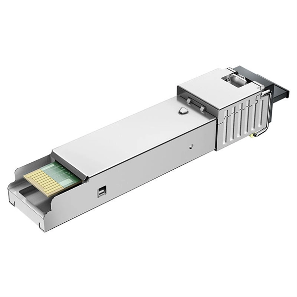
pigtails can be divided into single-mode (colored yellow) and multimode (colored orange) fiber. Multimode pigtails use 62.5/125 micron or 50/125 micron bulk multimode fiber cables and terminated them with multimode fiber optic c. pigtails can be divided into single-mode (colored yellow) and multimode (colored orange) fiber. Multimode pigtails use 62.5/125 micron or 50/125 micron bulk multimode fiber cables and terminated them with multimode fiber optic connectors at one end. 10G multimode fiber cables (OM3 or OM4) are also available in optic pigtails. The jacket color of 10. Fiber Optic Pigtails, In fiber optic cable installation, how cables are attached to the system is vital to the success of network. If done properly, optical signals would pass through the link with low attenuation and little return loss. pigtail offers an optimal way to joint optical fiber, which is used in 99% of single-mode applications. This pos. According to different types of pigtail cable connector terminated at the end, there are LC fiber pigtail, SC pigtail, ST pigtail, FC pigtail, fiber pigtail and so on. With different structures and appearance, each of them has their own advantages in different applications and systems. Let's go through some widely used ones. SC Pigtail: SC pigtail.
[PDF]

Traditional turbidity monitoring methods involve the manual collection of water samples at set locations and times followed by laboratory analysis, which are labor intensive and time consuming. Fiber-optic measurement permits real-time, in situ turbidity monitoring. But the current technology is. This paper presents the development of an optical fiber sensor system for multiparametric assessment of temperature and turbidity in liquid samples. The sensors are based on the combination between fiber Bragg gratings (FBGs), intensity variation and surface plasmon resonance (SPR) sensors. Electrical, Electronic and Communication Engineering Dept. ; bFiber Photonics Department, UMR CNRS/University of Limoges 7252, 123 Avenue Albert Thomas, 87060 Limoges cedex, France; c“Grupo de Ingeniería fotónica”, Avenida Los Castr s. Turbidity is caused by the presence of suspended particles, organic matter, and chemicals, and is widely measured in natural resources, irrigation water, the food and beverage industry, and drinking water [1,2,3]. As an important water quality parameter, turbidity not only indicates the efficiency. Create a new folder below. Sensors were designed in two versions: for examination of liquid samples and for monitoring of transparency in the flow of liquids ('on-line'.
[PDF]
Main cost drivers include cable grade (indoor vs outdoor, armoured), distance, and labor for trenching, splicing, and termination. This guide presents ranges in USD and practical price estimates to help budget planning. Indoor OM3/OM4 vs outdoor armoured increases price. For fiber cable materials only, expect $0. 52 per foot for wholesale bulk purchases, or $1 to $6 per foot at retail. The wide price range reflects differences in fiber strand count, outer jacket construction, and application type. 13 per foot. Buyers typically pay for fiber optic cable by length, fiber type, and installation complexity. Whether you're planning a national fiber rollout or sourcing cables for enterprise infrastructure, understanding how fiber optic cable pricing works can help you budget more effectively and make better. Owners and buyers often pay for fiber optic cable by the meter, plus labor, connectors, and installation. First and foremost, fiber cables are either singlemode or multimode. Singlemode cables with a small core diameter of 9 microns use high-power laser light sources to support high-speed.
[PDF]
The International Electrotechnical Commission answers the first question with IEC 60332, “Tests on electric and optical-fibre cables under fire conditions – Part Tests for vertical flame propagation. ”. The cable must meet the requirements of the National Electrical Code® (NEC®) Section 770. 1 Plenum Applications - Applicable Flame Test: NFPA 262. Cables shall be listed OFNP. 2 Finished cables shall conform to the applicable performance requirements of the Insulated Cable Engineers. All conductors or cables shall be installed using any of the metal wiring methods permitted by 708,10 (C) (1) and, in addition, shall comply with the following, as applicable: All cables for fire alarm, security, signaling systems, and emergency communications shall be shielded twisted pair cables. es operation for 3 hours in fires up to 1000C. It eliminates the need f OM4) starting from 2 all the way to 48 fibers. Our cables are stocked res to ensure communication systems integri e charged with enforcing the Life Safety Code. In many states the AHJ are the state fire marshals ho have local. This short guide explains the commonly used materials — LSZH and PVC — how industry fire-rating systems (plenum, riser, vertical flame tests) work, and practical tradeoffs so you can pick the right cable for the space and code requirements. Certified to B2ca CPR and FE180 fire-resistance standards, these cables maintain optical integrity under extreme.
[PDF]
This article provides a step-by-step guide on terminating fiber optic cables, covering essential tools, methods, and best practices. High-speed fiber optic networks form the backbone of modern communications systems. more Audio tracks for some languages were automatically generated. This is where the of the end of fiber and the ferrule that holds it in the connector are polished to give a uniformly flat and clear surface for the best optical performance and minimal signal loss. Optimal performance can be achieved by following the correct process for termination of the fiber circuit—a task which requires the use of a wide range of. Terminating fiber optic cables is a critical skill for telecommunications technicians. Proper termination ensures reliable network performance and minimal signal loss across fiber infrastructure.
[PDF]
Fiber Breakage: Single-mode fiber optic cables can be prone to fiber breakage, which can result in signal loss. Fiber breakage can occur from physical damage, such as bending or crushing the cable. This can cause signal attenuation and may even result in signal loss. To avoid bend loss, it is important to follow the minimum bend radius specified by the cable manufacturer. NEATEL's The Single-Mode (SM) Breakout Indoor Fiber Cable is designed for high-performance, secure fiber optic connectivity in indoor environments. Unlike tight-buffered fiber cables, this breakout-style cable features multiple individually reinforced sub-cables (typically 2. Tension and stress: Fiber optic cables can be damaged if they are subjected to too much tension or stress, as this can cause the fibers to break. Fiber design and transmission technology have collaboratively evolved to increase bandwidth. Dig-ups dominate! Cablers have very little influence on the majority of causes of cable field failures. While a small percentage, we can examine the “intrinsic” cable failures and what is done to prevent. Recommendation ITU-T L. 103 describes characteristics, construction and test methods for optical fibre cables for indoor applications. In order for an optical fibre to perform appropriately, characteristics that a cable should have been described. Also, the method of determining whether the cable.
[PDF]

One of the most common ways to test fiber optic cables is with a light source, which emits light through the cable to detect any potential problems. LED light sources emit. Fiber optic cables are a top choice for high-speed communication systems and can also serve as sensors to measure and monitor various quantities. Modern. Document the end-to-end results for the fiber optic segment you just tested. Related: Data Center Cabling Best Practice Guide Using optical time domain reflectometer testing, you'll measure the length of the fiber optic cable, attenuation, and any events occurring on that fiber segment. Events are. A photodiode is a semiconductor diode sensitive to photon radiation, such as visible light, infrared or ultraviolet radiation, X-rays and gamma rays. It produces an electrical current when it absorbs photons. This can be used for detection and measurement applications, or for the generation of. A typical fiber optic communication system consists of three primary components: a transmitter, a fiber optic cable (the transmission medium), and a receiver. The transmitter usually incorporates a Light Emitting Diode (LED) which converts digital binary data into light waves. The studies cover fiber optic components that have standard SMA connectors to couple with SMA-SMA connectorised PMMA (plas otodiode and a phototransistor. It has a built-in optical power meter an the associated power supplies. Apart from LPS04, the accessories.
[PDF]
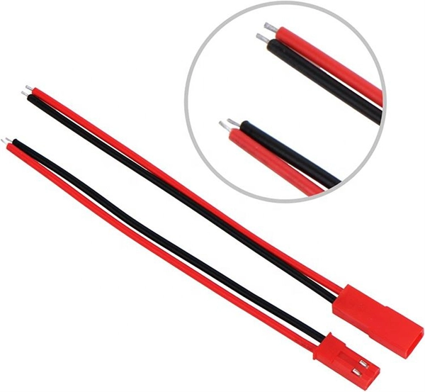
The wiring inside the panel is neatly organized with red wires for live connections, black wires for neutral, and yellow-green wires for grounding. At the bottom, there is a terminal block where incoming and outgoing wires are connected. Welcome to this live training session! ⚡ In today's tutorial, I'll be demonstrating how to arrange cables neatly inside a distribution bo. more See what others said about this video while it was live. This switch allows the user to choose the power source. Below the switch, there are several miniature. An electrical panel box, also known as a breaker box or a distribution board, is a crucial component of any electrical system. It serves as a central hub for distributing electricity throughout a building, ensuring that power is delivered safely and efficiently to all the required locations. A neat, well-organized subpanel bundles wires to conserve space and improve access. Ideally, wire groups are installed in layers and wires are bent at right angles to buses or breakers. Label short sheathing sections (slugs) to indicate which circuits wires serve. A distribution box, also known as a.
[PDF]
This article is about the Internet Outages Map, which provides a visualization of global internet health over the last 24 hours. It also includes information on how to use this map and what data it collects, as well.
[PDF]
The cost to install fiber optic cable ranges from $1. 50 to $42 per foot, with installation costs accounting for 60-80% of total project expenses. According to the Fiber Broadband Association's 2025 report, median costs are $8 per foot for aerial builds and $18 per foot for. Fiber optic cable installation costs between $1,500 and $7,000 for your home, with prices varying by cable length and installation method. The installation type you choose and the layout of your property determine the total labor and materials needed for your project. You should account for permit. The initial cost of installing fiber optic cables can vary depending on the chosen installation method and specific project requirements. Total Project Costs: For commercial installations, expect costs ranging from $5,000 to $20,000 per mile for underground projects and from $40,000 to $60,000 per. Homeowners and businesses typically pay for fiber optic cable installation based on distance, conduit needs, and labor. The main cost drivers include material type, run length, trenching or aerial work, and any required permits or inspections. This comprehensive guide breaks down the factors influencing pricing, average expenses, and tips to get the best value in 2025. Clear insights help make informed decisions without unexpected surprises. Let's start by getting a better idea about the material cost. Understanding the fiber cable cost per foot is crucial before.
[PDF]

The machine is a hand-held free-to-height cable quick-attachment tool with internal components such as controllers that automatically complete all steps of cable tying. It can be widely used in the high-altitude operation in the field of communication engineering and is. Power Source: Rechargeable lithium battery Bundling range: 0-60mm Binding : can binding 1600 times for one time fully charger. Voltage: 12V Battery: 7800 mAh/group, Fully charged, one battery can work more than 1600 times, about 3 kilometers or more Battery installation mode: external and embedded. Delivery time is estimated using our proprietary method which is based on the buyer's proximity to the item location, the shipping service selected, the seller's shipping history, and other factors. Delivery times may vary, especially during peak periods. Buyer pays for return. Buy Newly Designed Second Generation High Altitude Optical Fiber Cable Bundling Machine for Efficient Network Installation at Aliexpress for. Find more 1420, 153713 and 1537 products. Enjoy ✓Free Shipping Worldwide! ✓Limited Time Sale ✓Easy Return. Maximum order quantity: 1 piece Customized logo (+ from /Min.
[PDF]
There are hybrid optical and electrical cables that are used in wireless outdoor Fiber To The Antenna (FTTA) applications. In these cables, the optical fibers carry information, and the electrical conductors are used to transmit power. These cables can be placed in several environments to serve antennas mounted on poles, towers, and other structures. According to Telcordia GR-3173, Gener. OverviewA fiber-optic cable, also known as an optical-fiber cable, is an assembly similar to an but containing one or more that are used to carry light. The optical fiber elements are typically individually. Optical fiber consists of a and a layer, selected for due to the difference in the between the two. In practical fibers, the cladding is usually coated wit. In September 2012, NTT Japan demonstrated a single fiber cable that was able to transfer 1 per second (10 bits/s) over a distance of 50 kilometers. Although larger cables are available, the highest stra.
[PDF]
This Report Provides In-Depth Analysis of the U. Fiber-Optic Cable Market Report Prepared by P&S Intelligence, Segmented by Type (Single-mode, Multi-mode, Plastic Optical Fibre), Cable Type (Loose Tube, Tight-Buffered, Ribbon, Armored, Simplex & Duplex Cable), Fiber Type. This Report Provides In-Depth Analysis of the U. The growth of market is attributed to factors such as proliferation of data centres and increasing deployment of 5G network. Increased broadband. The fiber optics industry is projected to reach USD 6. 8 billion by 2029 from USD 3. 4% from 2024 to 2029. Rapid expansion of data centers, cloud services, and 5G infrastructure is driving strong adoption of fiber optic solutions. Rising internet penetration and. Fiber optic cable market has emerged as vital part of the worldwide telecommunications and data transmission system. The fibre optic cables that carry the data by the use of light signals have a much greater advantage over traditional copper cables because they have a higher bandwidth, faster. Fiber optic cables are high velocity information transmission mediums that utilize slight strands of glass or plastic filaments to send data as light signals over significant distances.
[PDF]


